Where the project stalled
A commercial HVAC OEM was building a new air handling product around our LWPI-φ121×873-01 impeller. It is 873mm long and 121mm across, and its cross-flow impeller shaft is where this story goes wrong.
On performance and materials, the part already suited them. It gives 1000 to 1500 CFM, roughly 1700 to 2550 m3/h, in glass-filled AS+GF30% composite. Their tolerances were tight too. Radial runout under 0.7mm, and residual unbalance below 0.3g at 1200 RPM.
Then integration hit a wall.
Their chosen motor has a 6mm drive shaft, and our cross-flow impeller shaft did not match it. Meanwhile our standard impeller carries an 8mm by 22mm steel shaft. Two millimetres, and assembly becomes impossible.
The request that came back was refreshingly direct: change the shaft to 6 by 25, because 8 by 22 is too big. Urgent, and tied to a production schedule.
Validating a smaller cross-flow impeller shaft
Here the looks like a dimensional change on a drawing. In practice it is a question of mechanical integrity, so we treated it that way.
Why an adapter was refused
The obvious fix is a sleeve bridging the 6mm motor shaft to the 8mm bore. Nevertheless we rejected it.
An adapter adds a line to the bill of materials, a step to assembly, and a fresh source of imbalance on a wheel that must hold 0.3g. Basically, solving a fit problem by adding a part creates two more.
Checking that 6mm is strong enough
Meanwhile the real work was proving the thinner cross-flow impeller shaft. Torsional strength falls sharply as diameter drops, so this is never a formality.
Our engineers worked out torsional stress and deflection across the full range, up to the 1600 RPM test speed. The shaft carries the motor torque without failing.
Checking that it will not resonate
A separate worry is stiffness rather than strength. A thinner shaft bends more easily, which lowers the natural frequencies of the assembly. Consequently, a frequency landing inside the running range gives you vibration no amount of balancing removes.
Modal analysis showed the change moves no resonance into the normal running band. Meanwhile the shaft material stayed high-grade steel throughout.
What did not change
The blade structure in AS+GF30% is untouched, so airflow matches the original part exactly. Nothing needed retesting on that side.
Afterwards our engineers updated the master CAD model and issued a revision-controlled drawing, LWPI-φ121X873-02. It passed internal review, the papers went on file, and the customer confirmed their order against it.
Technical Specifications
Here the cross-flow impeller shaft dimension is the only line that changed. Otherwise every aerodynamic and balance figure below carries over from the original part.
| Parameter | Specification |
|---|---|
| New Model Number | LWPI-φ121×873-02 |
| Original Model Number | LWPI-φ121×873-01 |
| Impeller Diameter | 121 mm |
| Impeller Length | 873 ±2 mm |
| Shaft Dimensions (New) | Ø6 mm x 25 mm |
| Shaft Dimensions (Original) | Ø8 mm x 22 mm |
| Impeller Material | AS+GF30% (Acrylonitrile Styrene + 30% Glass Fiber) |
| Color | Black |
| Reference Airflow | 1700 – 2550 m³/h (1000 – 1500 CFM) |
| Maximum Test Speed | 1600 RPM |
| Balancing Specification | Residual unbalance ≤ 0.3g at 1200 RPM |
| Rotation | CCW (Counter-Clockwise) |
Technical Documentation
The following documents were central to this project, showing the transition from the standard part to the custom-fit solution. These drawings are essential for OEM quality assurance and incoming inspection teams.
Drawing LWPI-φ121×873-01.pdf: This document specifies the original standard component with the Ø8 mm x 22 mm shaft.
Drawing LWPI-φ121×873-02.pdf: This is the final approved drawing detailing the custom-engineered Ø6 mm x 25 mm shaft requested by the customer.
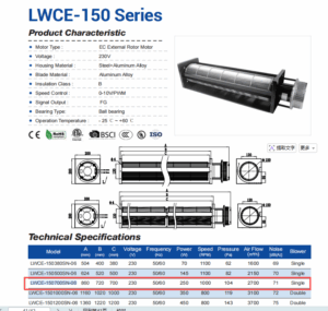
 : This image from the initial customer communication clearly illustrates the fitment issue that initiated the engineering change request.
Why the change was handled in house
On a change this small and this urgent, four things mattered.
- Specified, analyzed and approved quickly. A critical mechanical change went from request to approved drawing in a fraction of the 12 to 18 months imported European brands commonly quote, which kept the customer production schedule intact.
- The analysis happened here. Our own engineers checked the torsional strength and the modal behavior under our ISO 9001 system. Consequently nobody had to take a supplier assurance on trust.
- A direct-fit part, not a workaround. Delivering the correct shaft removed the need for adapters or for re-sourcing the motor. That reduced the customer bill of materials and simplified assembly at the same time.
- Documentation their systems can hold. The project ended with a revision-controlled drawing. That is what procurement and quality need for PLM and ERP records, rather than an email describing a change.
Browse our cross-flow impeller range, the cross-flow fan section for complete assemblies, or the AC cross-flow and DC cross-flow series. Balance grades are defined in ISO 21940.
Questions about shaft modifications
How long does a shaft diameter change take?
Where only a drawing revision and minor tooling work are involved, first article samples usually follow within three to four weeks of confirmation. That sits inside our standard custom NPI framework, and well inside the timelines many European suppliers quote.
Is there a minimum order quantity?
Yes, custom components carry an MOQ to cover setup and tooling. For a cross-flow impeller this size, a first order is typically 50 to 100 units. Repeat rolling orders usually have a lower threshold, and terms are negotiable under a longer-term volume agreement.
Does the smaller shaft affect performance or certification?
Not aerodynamically, since the blades and diameter are unchanged, so the 1000 to 1500 CFM reference still stands. Furthermore, a component change like this does not directly affect system certifications such as CE or UL. We supply the mechanical data you need to update your own technical file.
Why check resonance rather than just strength?
Because a cross-flow impeller shaft can be strong enough and still be wrong. Reducing diameter lowers stiffness, which lowers the natural frequencies of the rotating assembly. If one lands in the running range, the fan shakes however well you balance it. In short, strength and stiffness are separate questions.
Technical Documentation & Resources

Got a duty point you need matched?
Tell us the airflow, the pressure and the space you have. Then we mark your duty point on a tested curve and send the drawing back. Meanwhile samples and custom spec sheets take up to 90 days. Since 1990 we have supplied OEMs across HVAC, refrigeration and industry.
🏆 ISO 9001 / ISO 14001 / ISO 45001 | CE (TÜV) | UL/ETL | ATEX Zone 21/22 | AMCA 210/211 / ISO 5801 tested
Choose the right cross flow impeller
Longwell manufactures 17 cross flow impellers in-house. Send airflow, static pressure and voltage — an engineer replies with a matching model, performance curve and price within one working day.