What the OEM needed solving
An OEM had already approved samples of our LWMI-φ50X350-01 impeller, 350mm long and 52.5mm across, and was moving towards production. Then a mechanical problem appeared. They had no cross-flow impeller mount that would fit.
Their chassis has a fixed mounting hole, first described as 21mm. The impeller has a 3mm shaft. So something had to sit between the two, and it had to do two jobs at once.
- Support the shaft in the cross-flow impeller mount and let it turn freely.
- Damp vibration, so noise and structural resonance stay out of the housing.
- Fit the existing aperture without modifying the chassis.
- Arrive as a documented part with a number, ready for their bill of materials.
The order tells you what they planned. Two hundred impellers complete with the mount, plus ten mounts on their own. Presumably for service stock, or for a pilot build.
This is not an air problem at all. Rather, it is a fitting problem with a noise problem hiding inside it.
Designing the cross-flow impeller mount
Here the aim was to hold the impeller firmly while keeping shake out of the customer housing. Unfortunately those two aims pull against each other.
Why a metal bearing block was rejected
A rigid metal block is the obvious first idea, and it fails the second aim completely. It holds the shaft perfectly. Equally, it passes every tremor from the motor and the airflow straight into the sheet metal around it.
In a product that ends up in somebody living room, that is not good enough. The spec need not say so in writing.
The integrated approach
Instead our engineers designed one part, the LW-C08-50-01. It is a molded EPDM rubber cross-flow impeller mount with a precision ball bearing already fitted.
One part therefore does both jobs. The bearing carries the 3mm shaft with little friction, while the rubber body keeps that support away from the chassis.
Why EPDM
We chose EPDM for toughness and for lasting springiness. Rubber that hardens loses its damping. Consequently a mount gone stiff after two summers is worse than none at all.
It also holds up across the wide temperature swings an HVAC system creates. That is the same thinking behind our ThermoFlex approach elsewhere.
The geometry changed during design
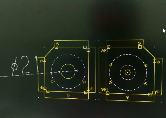
The first brief mentioned a 21mm hole. However, working through it with the customer produced a mount with a 12mm boss and a 30mm outer flange.
That shape seats more firmly in their final build. In short, it shows why an early conversation beats building exactly what the first drawing said.
Meanwhile the project ran as light development. A project manager took it, drawings followed, costs were worked out, and a quotation went out. No tooling charge, and no long wait.
Technical Specifications
The cross-flow impeller mount carries its own part number, since the customer wanted to order it separately as well as fitted.
| Parameter | Value |
|---|---|
| Model | LWMI-φ50X350-01 |
| Impeller Diameter | 52.5 mm (+0.5/-0) |
| Impeller Length | 350 mm (±0.3) |
| Shaft End Diameter | ø3 mm |
| Number of Blades (Z) | 22 |
| Rotation | Counter-Clockwise (CCW) |
| Material | Aluminum Alloy |
| Radial Runout Tolerance | ≤ 0.08 mm |
| Parameter | Value |
|---|---|
| Model | LW-C08-50-01 |
| Overall Diameter | ø30 mm |
| Mounting Boss Diameter | ø12 mm |
| Bearing Inner Diameter | ø3 mm (to fit impeller shaft) |
| Mount Material | EPDM Rubber |
| Components | 1x Rubber Mount, 1x Ball Bearing |
Technical Documentation
Finalized engineering documents were created to support the customer’s design-in and procurement processes. These files define the exact specifications for BOM integration and quality control.
LWMI-φ50X350-01.pdf
Mechanical drawing for the cross-flow impeller, detailing all critical dimensions, material specs, and balance tolerances for OEM system engineers.
LW-C08-50-01.pdf
Engineering drawing for the custom LW-C08-50-01 bearing and rubber mount assembly, which procurement managers use for ordering and quality teams use for incoming inspection.

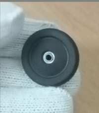
The image shows the installation context of the final LW-C08-50-01 assembly, demonstrating the intended fit and function within a sheet metal housing plate.

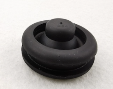
A detailed view of the custom-molded EPDM rubber mount with its pre-installed ball bearing prior to installation.
Why an accessory got proper engineering
In the end, four things made a small part worth engineering properly.
- Accessories get real development too. This was light development on a mounting part rather than a fan. The customer still received a documented, production-ready component, without the cost of pushing a simple part through a full 90-day NPI cycle.
- One supplier for both halves. Supplying the impeller and its cross-flow impeller mount together saved the customer procurement team from sourcing, qualifying and managing a separate vendor for bearings and molded rubber.
- Customization without punitive tooling charges. The mount was developed and quoted without the NRE charges European suppliers typically attach to custom tooling, which is what keeps a bespoke part viable in mass production.
- Deliverables you can act on. The project ended with finalised CAD drawings and a formal quotation, so engineering could add the part number and purchasing could raise orders immediately.
Browse our cross-flow impeller range, the cross-flow fan section for complete assemblies, or the AC cross-flow and DC cross-flow series. Vibration isolation practice is covered in the ASHRAE Applications handbook.
Questions about the mount assembly
What is the lead time for impellers supplied with the mounts?
After sample approval, an initial order combining an existing component with a new accessory runs 25 to 35 days at quantities of 200 to 500 units. Later orders benefit from established tooling and move faster, particularly under a rolling forecast.
Does the EPDM mount handle wide temperature ranges?
Yes. EPDM was specified precisely for that. It keeps its damping properties and its structure across roughly -40C to +100C, which comfortably covers the swings an HVAC system produces between a cold start and full load.
Can the mount be ordered separately?
Yes. It carries its own part number, LW-C08-50-01, and is independently orderable. This customer ordered 200 impellers alongside 210 mounts for exactly that reason. The mount will support any 3mm shaft, so it is useful beyond this one project.
Why does the rubber matter more than the bearing?
Because the bearing solves a problem everyone expects, whereas the rubber solves the one that appears after assembly. A rigid cross-flow impeller mount feeds shaft vibration into panels, and those panels then radiate it as noise. Killing that path at the mount is far cheaper than damping panels later.
Technical Documentation & Resources

Sizing something comparable?
Share the airflow, pressure, voltage and control interface, and we come back with a tested curve and a drawing. Meanwhile custom work runs to 90 days for spec sheets and samples. Since 1990 Longwell has supplied fans to HVAC and industrial OEMs.
🏆 ISO 9001 / ISO 14001 / ISO 45001 | CE (TÜV) | UL/ETL | ATEX Zone 21/22 | AMCA 210/211 / ISO 5801 tested
Choose the right cross flow impeller
Longwell manufactures 17 cross flow impellers in-house. Send airflow, static pressure and voltage — an engineer replies with a matching model, performance curve and price within one working day.