A battery energy storage cabinet can report an acceptable average temperature while one cell pocket is already much hotter than the rest. BESS cooling is therefore not only about removing total heat; it must control local temperature and gradients across cells, modules, racks, busbars, converters, and auxiliary equipment through every required operating state.
This guide gives storage-system and renewable-energy EPC teams a framework for fan selection, airflow design, sensing, control, redundancy, and verification. The BESS cooling solution overview is a discovery route, not project approval. A Longwell EC fan image establishes physical fan architecture only. It is not an installed BESS case or model recommendation. Final selection requires project heat loads, air path, resistance, thermal limits, environmental boundary, controls, safety basis, and measured results.
Follow the Complete Heat Chain
Cells generate heat during charge and discharge, while contact resistance, balancing electronics, power conversion, and auxiliary devices add other loads. Heat moves from each source into modules and rack air, then from cabinet air to the final heat-rejection interface. A fan influences only part of this chain. If contact, module passages, or the external heat exchanger limits transfer, increasing speed may not cool the hottest component.
Build separate thermal maps for maximum charge, maximum discharge, standby, state-of-charge balancing, hot ambient, solar exposure, and reduced-capacity fault states required by the project. Use the battery supplier’s allowable temperature and gradient limits, project duty cycle, validated model, and site ambient envelope. There is no universal cell temperature, airflow-per-kilowatt rule, or cooling-redundancy target.
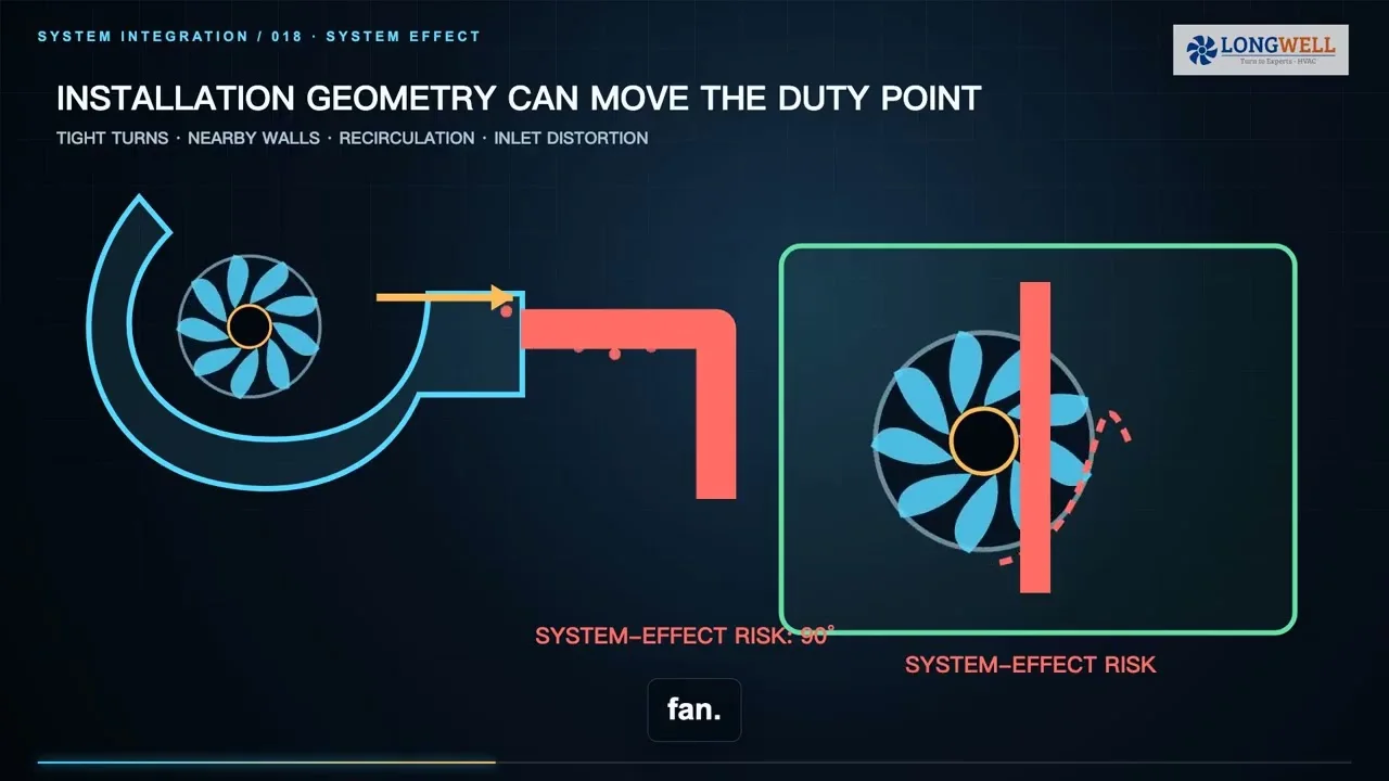
Engineer the Cabinet Air Path and Installed Resistance
Supply or conditioned recirculation air must reach the intended cell surfaces, pass through designed module gaps, collect heat, and return without short-circuiting. Empty cabinet volume is not automatically a useful flow path. Cables, busbars, shelves, guards, and partially blocked filters can create bypass routes and stagnant pockets.
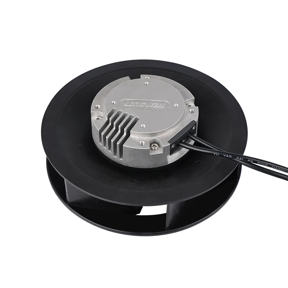
Inlet guards, filters, louvers, coils, ducts, rack passages, and outlet grilles form the installed system curve. Select the fan where its curve intersects this resistance at the defined air density and operating state; use the fan-curve operating-point guide to keep airflow, pressure, speed, power, density, and revision aligned. Maximum free-air airflow does not prove cabinet flow. Check both clean and loaded resistance, available envelope, voltage, control interface, sound, life, and service requirements.
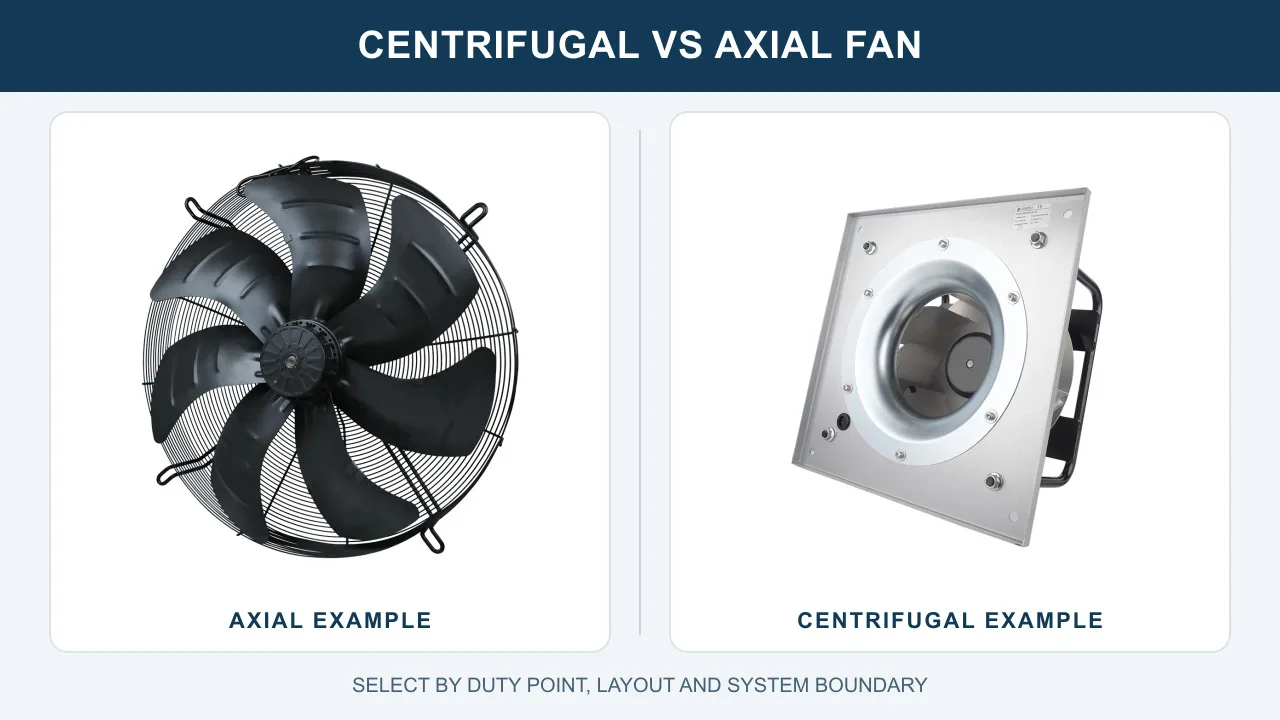
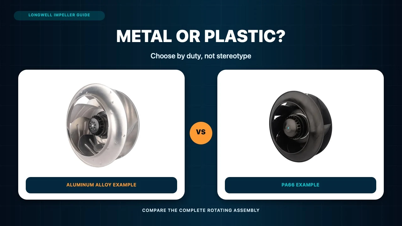
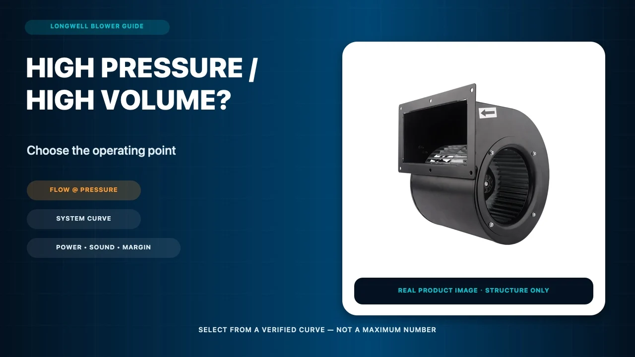
Centrifugal, axial, or other fan architectures may be appropriate depending on pressure, flow path, packaging, ingress strategy, and redundancy. The Longwell EC backward-curved fan family provides broad product-family context only. A category page or product photograph proves neither battery compatibility nor the required installed operating point.
Place Sensors Where Hotspot Risk Is Visible
Measure inlet conditions, return-air temperature, and known high-risk pockets. Combine air sensors with battery-management cell or module telemetry where the project provides it. A single sensor near a cold inlet can make an uneven system look healthy. Trend maximum temperature, spread between zones, and rate of change rather than relying only on an average.
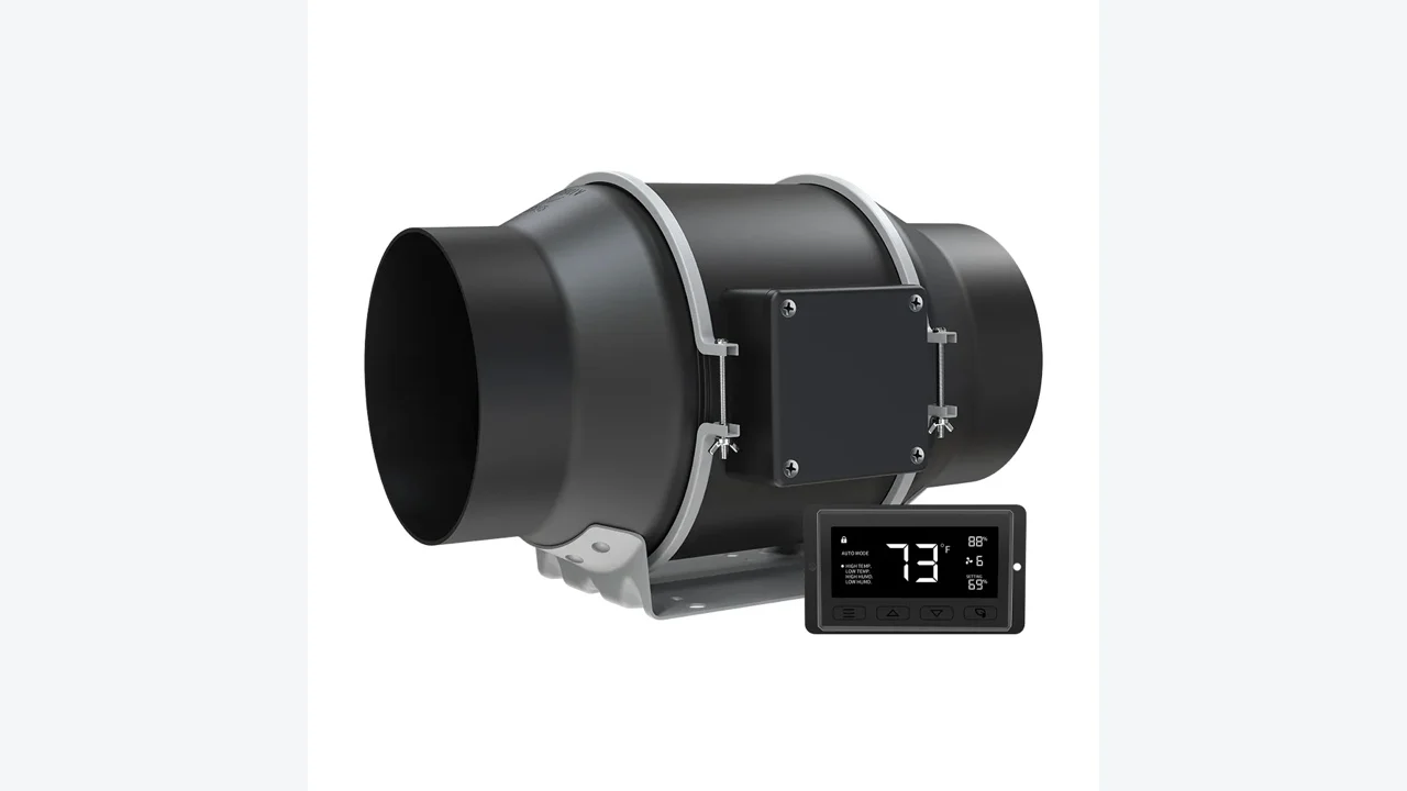
The control sequence should define fan enable, speed request, feedback, alarms, sensor-failure behavior, communications, and recovery after power loss. It must also identify which controller owns thermal demand and how it coordinates with the battery-management and external HVAC systems. A dashboard command or speed indication is not proof that air reached the hotspot.
Verify Redundancy and Environmental Protection Together
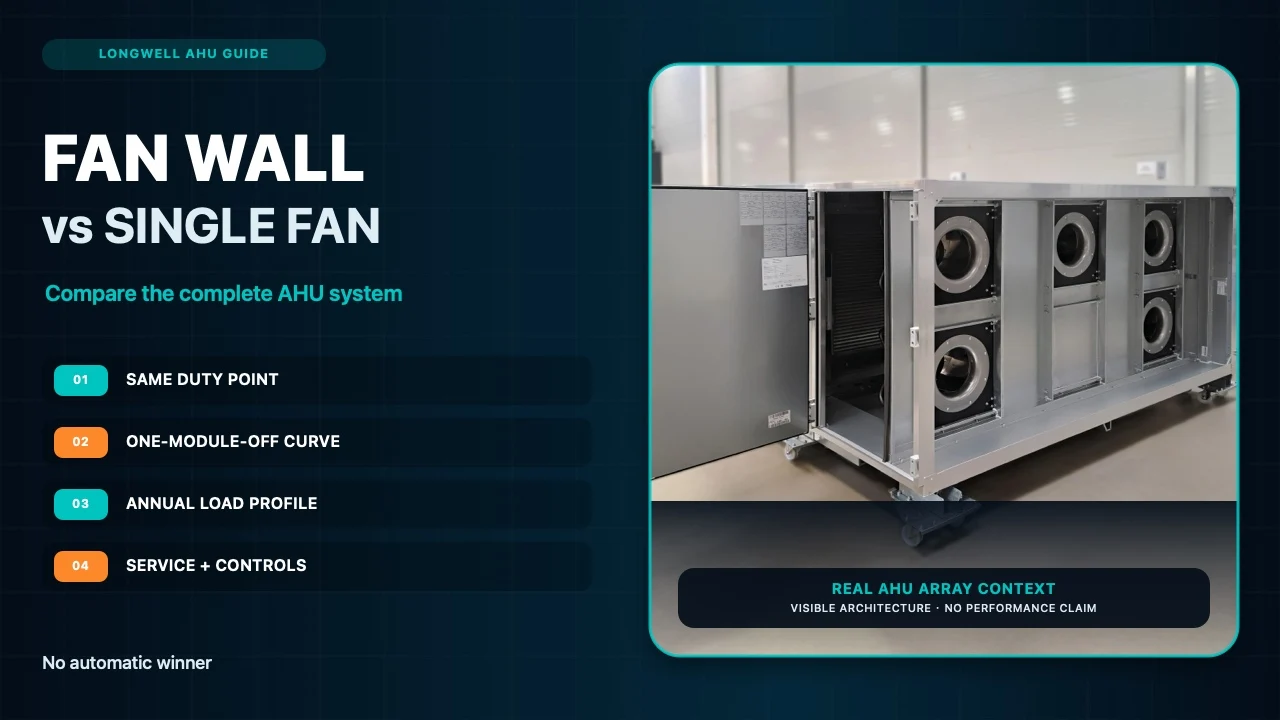
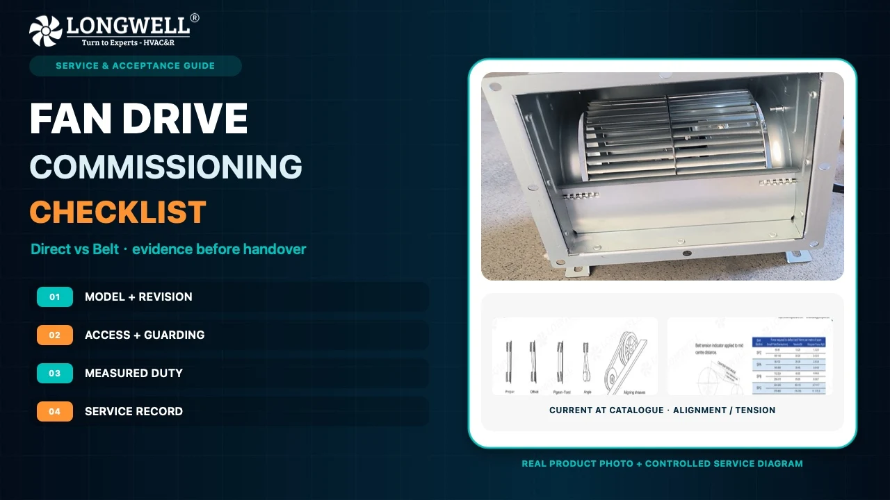
Redundancy must be demonstrated thermally. With one fan unavailable, verify that remaining airflow reaches every protected region and that temperatures stay within the defined limits over the required time. Check whether an idle fan creates reverse-flow bypass and whether modules share a power supply, controller, fuse, filter, or inlet obstruction. Quantity-based N+1 is not sufficient.
Ingress protection and airflow create a system tradeoff. Filters, labyrinths, and sealed heat exchangers add resistance, while outdoor equipment may face condensation, corrosion, low-temperature starts, dust, water, and solar heat. Do not weaken an enclosure rating by adding an unqualified opening. Coordinate filtration, drainage, materials, service access, pressure path, and the approved ingress strategy.
Keep Normal Cooling Separate from Emergency Safety
A circulation fan that manages normal cell temperature is not automatically a combustible-gas ventilation system, explosion-control measure, smoke-control device, or thermal-runaway solution. Those functions depend on cell chemistry, system listing, fire and propagation testing, hazard analysis, detection, controls, installation codes, and authority requirements. Normal cooling claims must never replace the project’s emergency safety design.
Commission across the representative thermal states, clean and loaded resistance, sensor faults, power recovery, and the defined module-out condition. Record fan command and feedback, electrical input, airflow and pressure where applicable, maximum and zone temperatures, rate of change, alarms, and recovery. Stop if hotspots, unstable control, overload, reverse flow, or unacceptable gradients develop.
The final duty package should include cell and module arrangement, normal and worst-case heat loads, allowable temperatures and gradients, ambient envelope, cabinet geometry, air path, resistance states, voltage, controls, sensor map, ingress requirement, sound target, module-out duty, validated results, and applicable safety basis. That evidence allows the fan, enclosure, and thermal-control system to be reviewed together without overstating what a fan alone can prove.