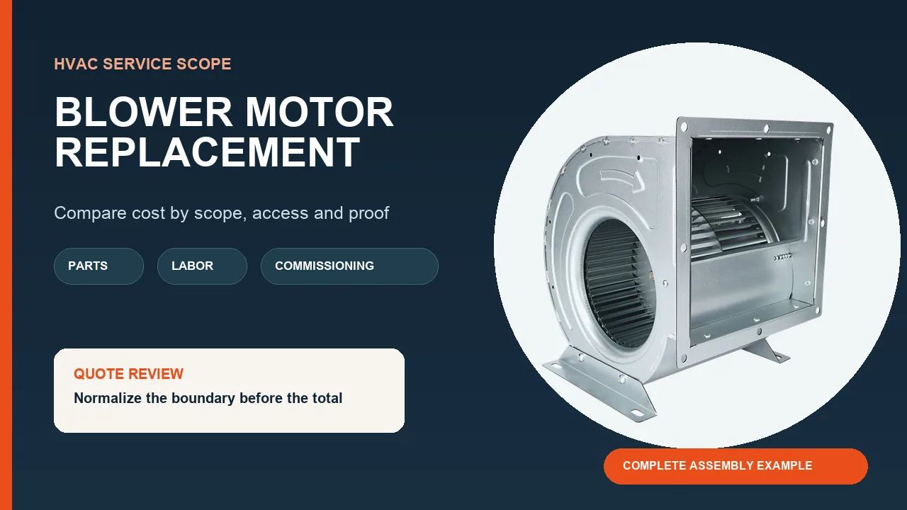
An indoor AC blower motor replacement is complete only when three records agree: the exact unit documentation, the old and proposed motor interface data, and the installed-load acceptance results. A motor that merely fits the bracket and turns can still have the wrong control architecture, rotation, shaft geometry, wheel position, or operating point.
This guide is for qualified HVAC and service personnel working on an air-handler or furnace blower assembly. It is not a universal wire-by-wire procedure, an outdoor condenser-fan guide, or approval for a particular replacement. Follow the exact equipment manual, replacement-motor instructions, site hazardous-energy procedure, and applicable requirements.
Confirm the motor is the failed component
Freeze the symptom before resetting the unit. Record the operating request, fault codes, sequence, actual blower response, airflow, noise, temperature, and any recent service. A missing supply or command, open safety circuit, control fault, damaged connector, restricted filter or coil, jammed wheel, failed capacitor where one is used, or incorrect speed selection can resemble a failed motor.
Do not order from one symptom or a resistance reading alone. The applicable unit diagnostic tree and motor documentation define the required checks. Energized measurements, panel access, capacitor work, and rotating-equipment tests belong to qualified personnel using rated instruments and the prescribed protective controls.
Build a replacement passport before ordering
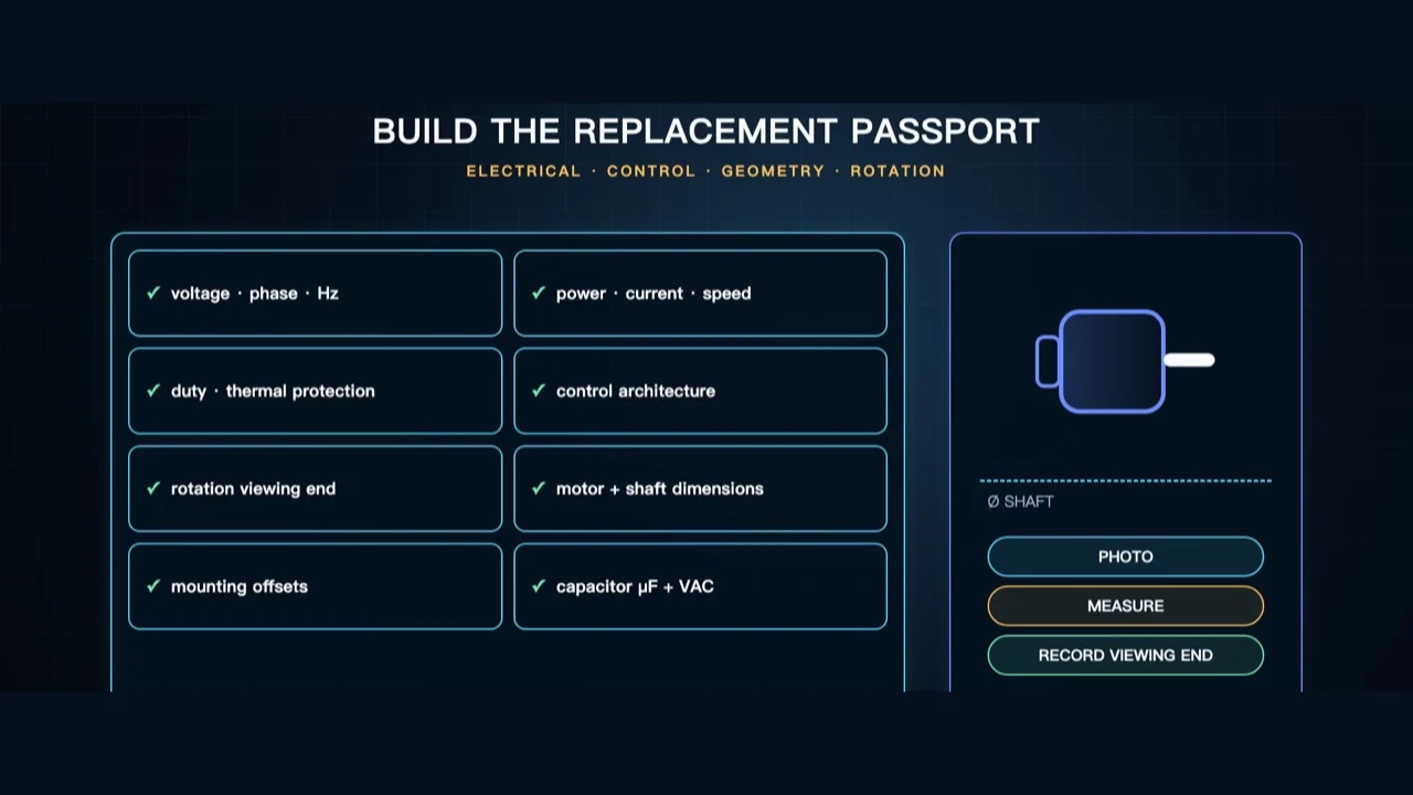
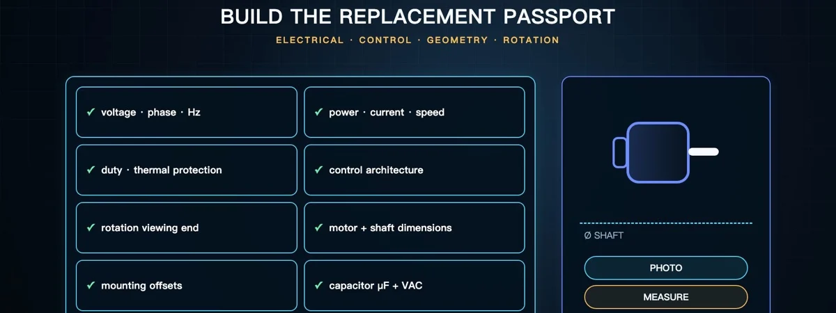
Record the unit model and serial number, blower assembly and wheel identity, old motor part and nameplate, and the service-parts reference. Capture voltage, phase, frequency, power, current, speed or control profile, duty, thermal protection, and whether the architecture is PSC, another capacitor motor, or electronically controlled. Rotation is incomplete unless its viewing end is stated.
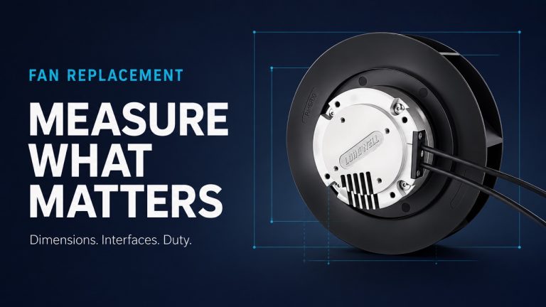
Measure the frame, mount, shaft diameter and usable length, connector or lead interface, and wheel position from a repeatable equipment datum. Record the motor-specific capacitor value and voltage rating only if the documented architecture uses one. The Longwell AC capacitor-motor family is a family-discovery route, not evidence that a listed motor fits this unit.
Create a verified safe state and conductor map
Use the site energy-control procedure to identify every source, isolate it, apply lockout or tagout as required, control stored energy, and verify de-energization with an appropriate method. A thermostat command, keypad stop, open contactor, or “try start” is not physical isolation. Never defeat an interlock or short a capacitor with an improvised tool.
Before disconnecting anything, photograph terminal labels, connector orientation, grounding, unused leads, and protected wire routes. Label conductors and reconcile them with the exact unit diagram and replacement instructions. Wire colours are not a universal pinout, and the old physical arrangement does not override a current controlled diagram.
Preserve the wheel-to-shaft evidence
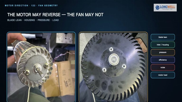
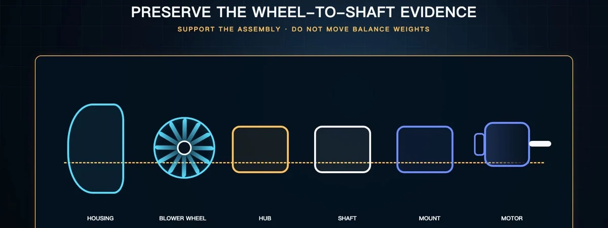
Support the blower assembly before removing its final restraint. Mark and measure the wheel’s axial position from the manufacturer’s stated datum, note hub orientation and shaft engagement, and preserve balance weights. Inspect the wheel, inlet, housing, mounts, and hub for damage that could explain the original symptom or harm the replacement.
Use the equipment-approved removal and transfer method. Do not hammer the shaft, lever against thin blades, or treat a generic puller method as universal. Protect the wheel and bearing path, and retain any specified fastener, shaft-flat, key, or torque requirement for reassembly.
Match the complete electrical and mechanical interface
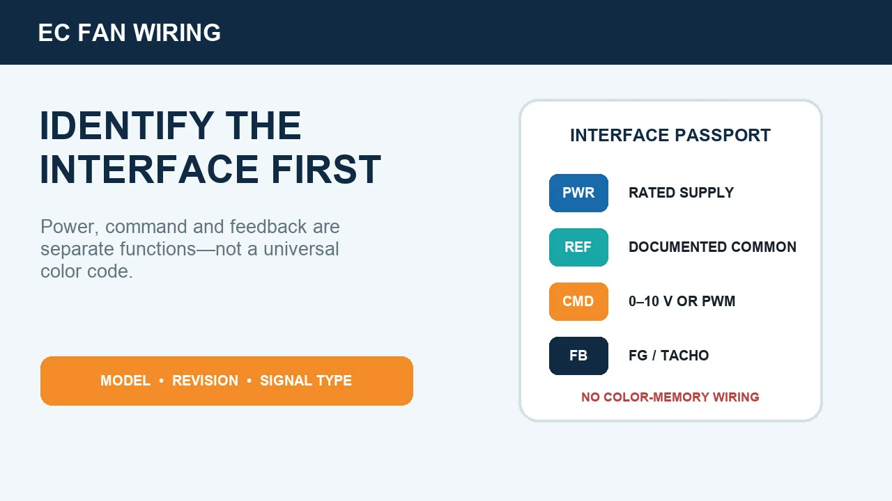
Approve the candidate only after its current application information matches the supply, control method, output and speed range, duty, rotation reference, thermal protection, mounting, shaft, connector, cooling, and environmental envelope. For a PSC design, use only the capacitor specification stated for the replacement motor and approved application; replacing a capacitor “as a matter of routine” is not a substitute for evidence.
An ECM is a different controls decision, not a more efficient drop-in assumption. The EC motor overview can explain the architecture, but only the equipment and replacement manufacturers can establish the required control profile, harness, programming, and application approval.
Restore rotation, wheel position, and clearance
Install the motor and wheel to the documented rotation viewing end, axial datum, inlet and end-plate clearances, mount orientation, wire route, grounding, and fastener requirements. Confirm that unused conductors are individually secured as directed and cannot reach the wheel or sharp cabinet edges.
While the assembly remains isolated, rotate it by hand through several turns. Stop if the wheel rubs, binds, shifts, or appears eccentric. This mechanical check can reveal an incorrect wheel position or damaged assembly before power, but it does not prove electrical compatibility or installed airflow.
Use a controlled test-energy sequence
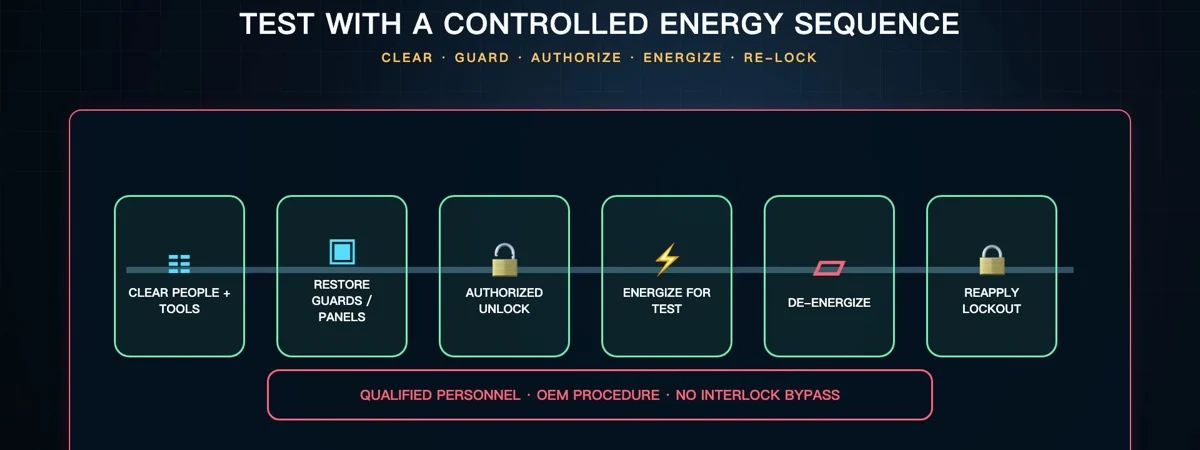
When testing requires temporary energization, follow the authorized sequence: clear tools and people, restore the guards or panels required for the test, remove energy-control devices only under the procedure, energize for the defined test, then de-energize and reapply energy control before any adjustment. Do not reach into a moving blower or bypass a door switch to simplify the test.
Under the required installed configuration, record supply voltage, running current, commanded and actual speed where available, vibration, sound, temperature, airflow or an approved proxy, and pressure. Compare each result with the exact unit and motor limits. A fan curve guide explains duty-point reasoning; it does not replace unit-specific acceptance data.
Release a repair record, not just a running motor
The handover should identify the old and new parts, document revisions used, conductor photographs, rotation reference, wheel datum, clearances, capacitor data where applicable, and before-and-after commissioning readings. Record any unresolved deviation instead of converting it into a verbal assumption.
If the motor exceeds a limit, the wheel rubs, airflow is not restored, or the original failure cause remains unexplained, stop and investigate. A defensible replacement ends with traceable evidence that the indoor blower assembly is safe, correctly matched, and operating within the controlling limits.
Choose the right blower
Longwell manufactures 247 blowers in-house. Send airflow, static pressure and voltage — an engineer replies with a matching model, performance curve and price within one working day.