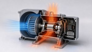
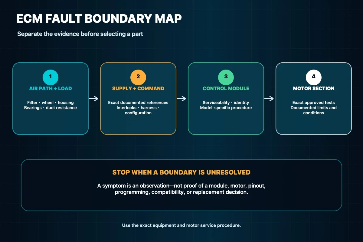
A stalled or erratic ECM blower does not identify the failed part. The same complaint can begin in the air path, rotating assembly, equipment controls, harness, electronic module, motor, or configuration. A useful diagnosis therefore separates those boundaries in a controlled order and records what was actually observed before anyone selects a replacement.
This guide is for qualified service personnel working from the exact equipment and motor documentation. It offers a decision structure, not universal test values, connector pinouts, or permission for energized DIY work. The video below follows the same evidence-first approach.
Define the fault boundary before testing parts
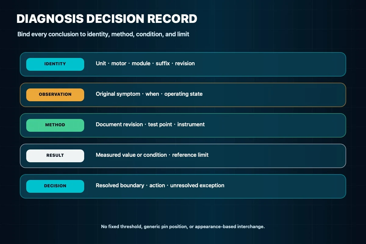
Begin with the equipment model, serial number, product revision, installed motor identity, module identity, and every visible suffix. Record the service-document revision and the original symptom in plain language: when the blower is requested, what it does, how long the condition lasts, and whether the complaint changes with operating mode. Do not turn that symptom into a diagnosis yet.
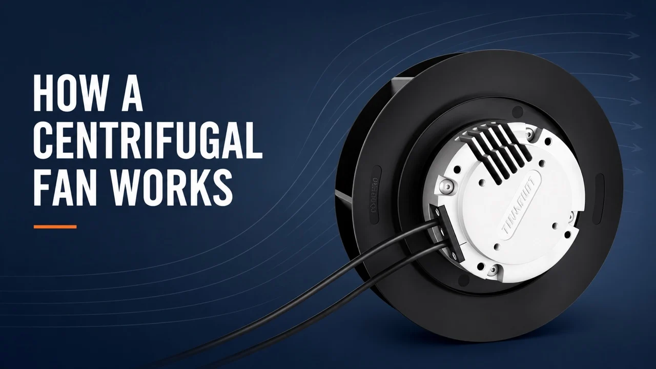
An EC motor overview can help explain why electronics and motor construction belong to one assembly, but it cannot establish the control method or test sequence for a particular unit. Those details must come from the controlled literature for the exact equipment and motor.
Preserve the as-found evidence
Before disconnecting anything, document the connector locations, harness routing, grounding or bonding provisions, wheel position, mounting, controller settings, and any displayed or stored diagnostic information. Note signs of moisture, heat, corrosion, abrasion, loose terminals, contact, contamination, or prior repair. A photograph is useful when it is tied to the correct unit and date.
Apply the site’s hazardous-energy procedure before contact with conductors or rotating parts, and follow the equipment instructions for stored electrical energy. A control command is not an energy-isolating means. If the approved procedure requires energized measurement, that work belongs to qualified personnel using the specified access arrangement, instruments, protective measures, and test points; this article does not supply an alternative method.
Separate the air path and mechanical load
With the assembly in the safe state required by the service procedure, inspect the filter, coil, wheel, housing, dampers, duct path, and other components that can change resistance or load. Check the rotating assembly using the exact manual method. Obstruction, contact, contamination, damaged wheel geometry, bearing condition, or a system restriction can change the symptom without proving an electronic failure.
Airflow and pressure observations only become useful when the test state and measurement locations are defined. This fan curve guide explains the relationship between airflow, pressure, and operating point, but a general curve is not an acceptance limit for the installed blower. Compare field observations only with the equipment-specific procedure or approved design record.
Verify supply and command as separate evidence
Many ECM systems have both a power path and a command or communication path, but their form varies by design. Use the wiring diagram and service sequence for the exact unit to identify the documented reference points. Confirm the required conditions in the order the manufacturer specifies, including interlocks, operating request, harness condition, connector engagement, and configuration where applicable.
Do not copy a voltage, waveform, jumper, resistance, pin position, wire color, fault-code meaning, or default-speed behavior from another ECM family. If supply or command evidence is missing or ambiguous, keep the diagnosis upstream and correct or escalate that boundary before judging the module or motor.
Distinguish module evidence from motor evidence
First determine whether the electronic section is separately serviceable, paired to a specific motor, or integrated into a controlled assembly. A substitution test is acceptable only when the exact service literature authorizes it and the replacement module, programming, configuration, and connector identity are all controlled. A physically fitting module is not a known-good reference.
For the motor section, perform only the tests specified for that exact design. If the manual calls for winding, insulation, sensor, or rotation checks, use its isolation steps, instruments, reference conditions, and limits. Generic statements such as “low and balanced,” a fixed percentage difference, no reading to a frame, or a familiar smell are not conclusive across ECM designs. Record the readings and the document limits rather than converting an impression into a pass or fail.
Make a repair decision that matches the evidence
A defensible decision names both the failed boundary and the evidence that excluded the others. If the air path, mechanics, supply, command, connector, or configuration is not yet within its documented state, address that issue and repeat the controlled sequence. If a module- or motor-specific test is outside its exact published limit, follow the corresponding manufacturer service path. When the result remains inconclusive, stop and escalate instead of swapping parts until the symptom disappears.
For sourcing, provide the complete equipment, motor, and module identities; suffixes and revisions; connector and control method; mechanical envelope; application duty; environment; and required validation record. The current LONGWELL ECM blower-motor page is a product-identity and inquiry route only. It does not prove that either listed model replaces an installed motor or matches an unknown controller.
Commission the resolved system and close the record
Reassemble the unit with its required guards, panels, routing, strain relief, seals, settings, and protective features. Plan the restart state before restoring energy. Observe only the items and measurements required by the approved procedure, stop on any mismatch or unexpected behavior, and reapply energy control before further contact.
The final record should connect the original symptom, unit and component identities, document revision, inspection findings, measurements with their test conditions, corrective action, configuration, restart observations, unresolved exceptions, technician, and date. That record supports the next decision without promising a universal diagnosis, interchange, performance gain, service life, or customer result.