A CFM calculator can return a precise-looking answer from the wrong method. Room air changes, occupied-space ventilation, and industrial source capture solve different problems. Forcing all three into one universal formula can produce an airflow that is mathematically tidy but technically inappropriate.
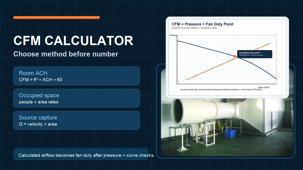
The correct calculation starts by choosing a mode, documenting the source of every rate, and keeping units visible. It then defines normal and peak scenarios, make-up air, and system resistance. Calculated airflow becomes a fan duty only after it is paired with static or total pressure and checked on an exact fan curve.
Choose the Calculation Mode Before Entering Numbers
The air-change method estimates how often an equivalent room volume is replaced. A people-and-area method develops an outdoor-air starting quantity from occupancy and floor area. A source-capture method estimates the exhaust needed to intercept a contaminant or heat source before it spreads.
These methods are not interchangeable. A room may require more than one analysis, but each result keeps its own purpose and boundary. Select the governing operating scenario rather than adding every number blindly as if all were independent clean-air deliveries.
Record the adopted code, process standard, owner requirement, or qualified risk assessment that supplies each input. A calculator should not invent ventilation rates or turn an online rule of thumb into a universal requirement.
Calculate Room Air Changes With Visible Units
Measure the clear inside length, width, and average height. A teaching room measuring 20 feet by 15 feet by 10 feet has a volume of 3,000 cubic feet. For an illustrative six air changes per hour, multiply 3,000 by six and divide by 60 minutes. The result is 300 CFM.
The formula is CFM equals room volume in cubic feet multiplied by ACH and divided by 60. In metric form, cubic metres per hour equals room volume in cubic metres multiplied by ACH. To convert cubic metres per hour to CFM, divide by approximately 1.699.
The six-ACH input and 300-CFM result demonstrate the arithmetic; they are not a universal ventilation prescription. The model also assumes room mixing is adequate for an air-change approach to be meaningful. Keep dimensions and units visible because entering feet in a metre field can create a convincing but false result.
Use People-and-Area Inputs for Occupied Spaces
Some occupied spaces use a breathing-zone structure based on a people rate multiplied by the number of people, plus an area rate multiplied by floor area. The applicable rates depend on occupancy category and the adopted requirements. They should be sourced and documented rather than guessed.
Additional corrections may be required for air-distribution effectiveness, system type, outdoor-air fraction, or local exhaust. These corrections remain part of the selected method and should not be silently replaced by a convenient ACH value.
Occupancy also varies with time. Define normal and peak populations and the control response. The design scenario should represent a credible simultaneous condition rather than an impossible sum of unrelated maximums.
Treat Source Capture as a Process Problem
Welding fume, vapour, dust, heat, and odour may require local exhaust that captures the source before it disperses through the room. A starting geometry relationship is airflow equals capture velocity multiplied by effective opening area. The required velocity and hood geometry are process-specific.
Cross-drafts, enclosure, worker position, duct entry loss, air cleaning, discharge location, contaminant properties, and safety requirements all affect the final design. Hazardous processes require qualified industrial-ventilation guidance and applicable risk controls; choosing a high ACH at random is not an adequate substitute.
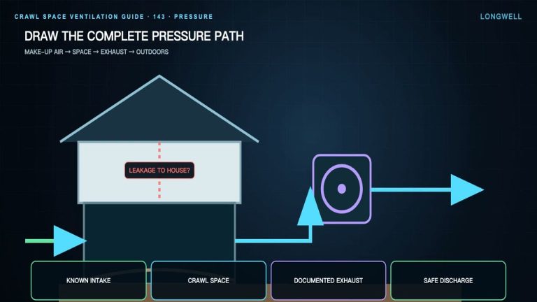
Exhaust also needs intentional make-up air. Without it, doors, combustion equipment, building pressure, and hood capture can behave differently from the calculation. Define which hoods and machines run together, including normal, peak, staged, and emergency modes.
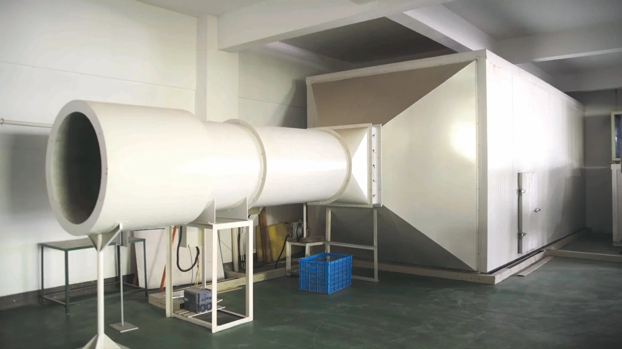
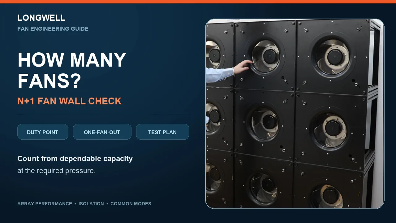
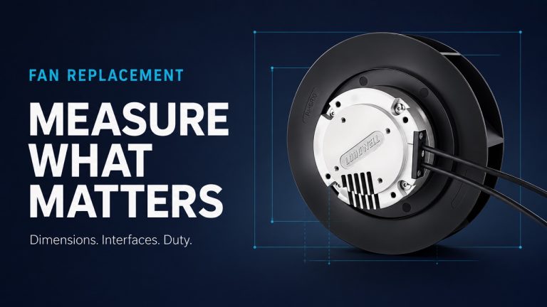
If the application is a ducted room or equipment ventilation path, public product-family pages such as inline duct fans and centrifugal blower fans can help frame the architecture after the method boundary is clear. They do not replace the airflow-pressure calculation or approve a specific model.
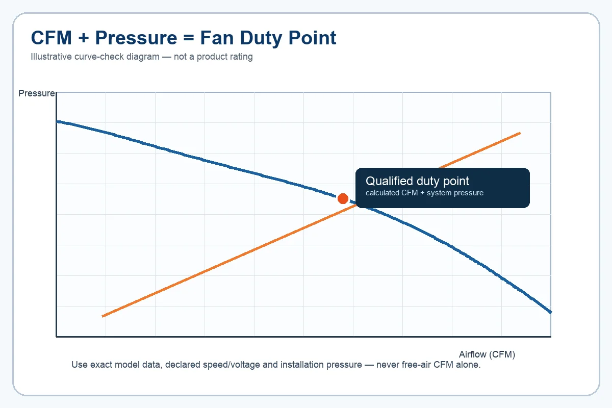
Turn Calculated CFM Into a Pressure-Qualified Fan Duty
Airflow alone does not select a fan. Add the pressure losses from filters, coils, ducts, elbows, dampers, grilles, hoods, air-cleaning equipment, and discharge components at the calculated flow. State whether the resulting duty uses static or total pressure.
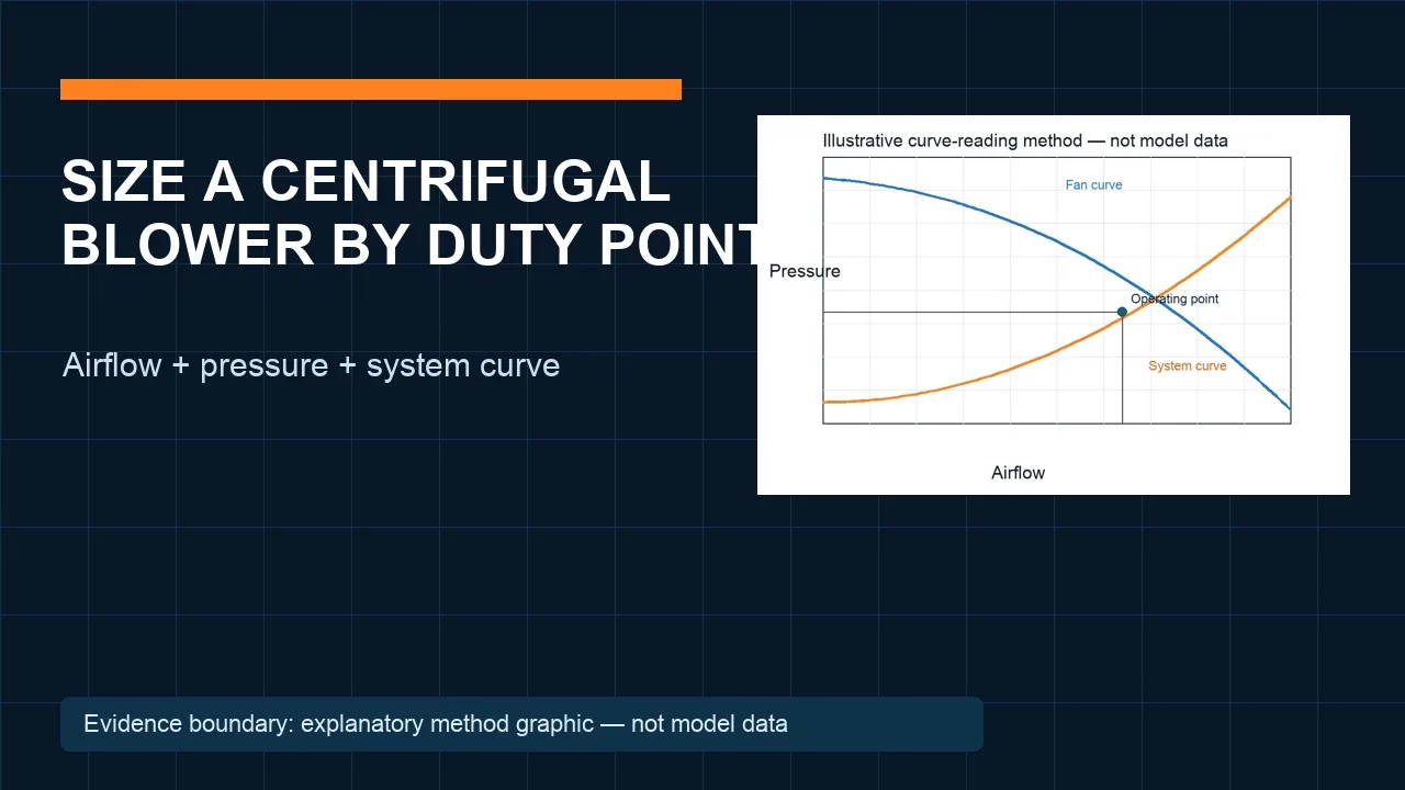
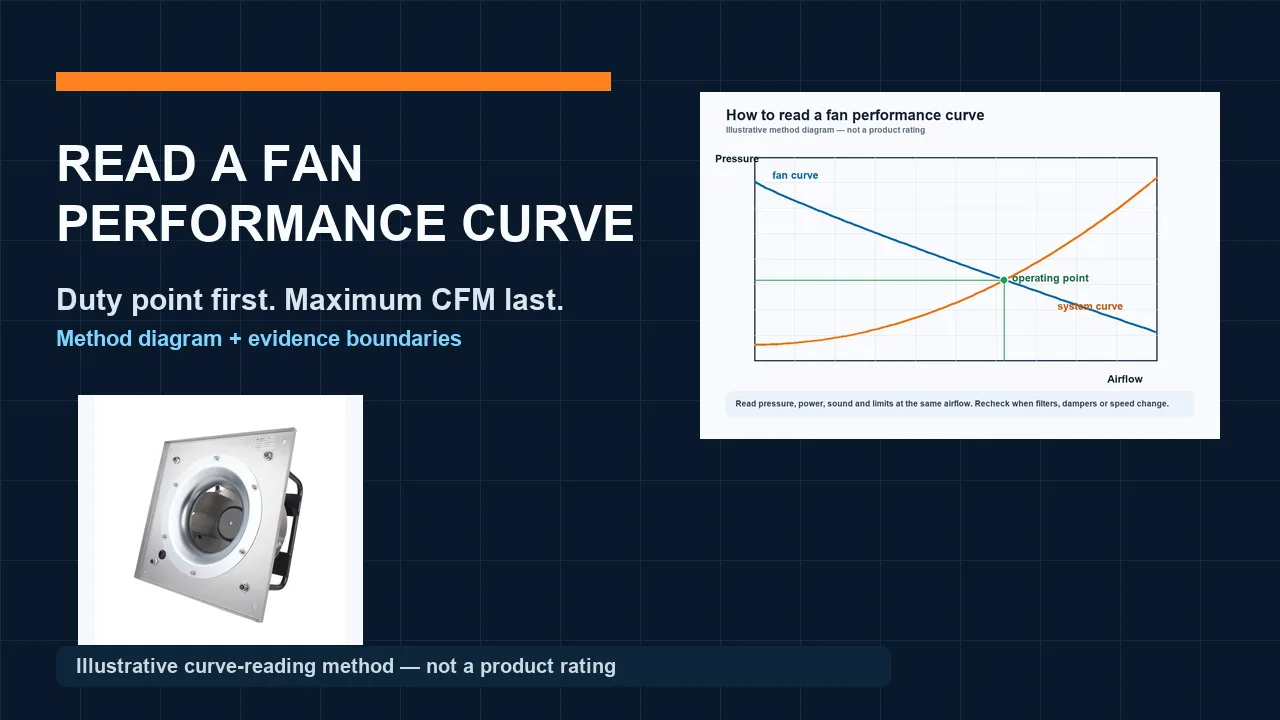
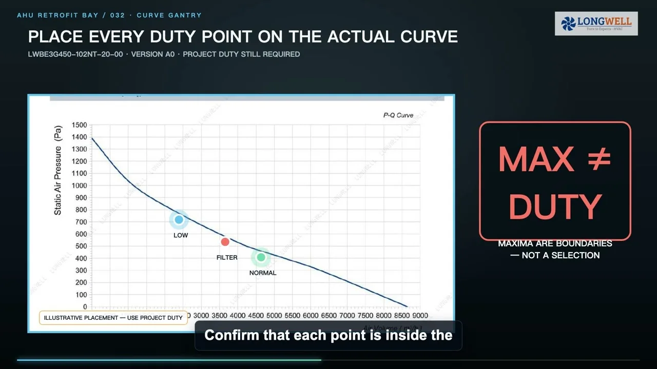
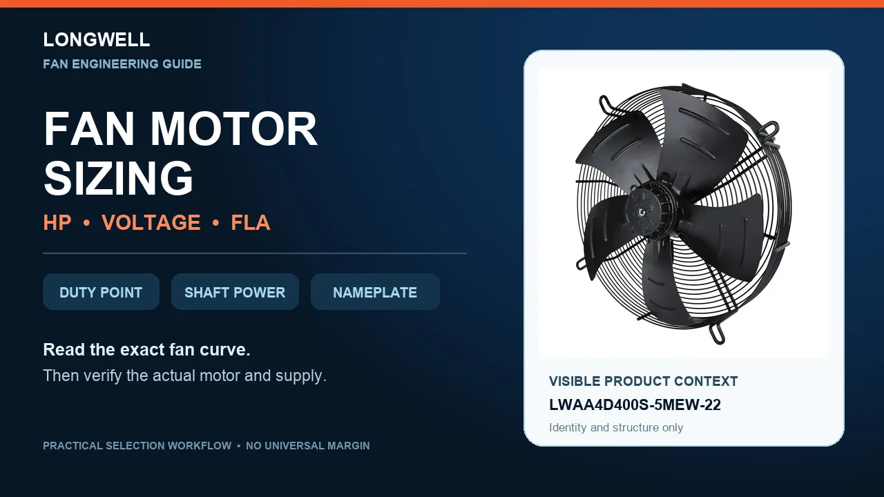
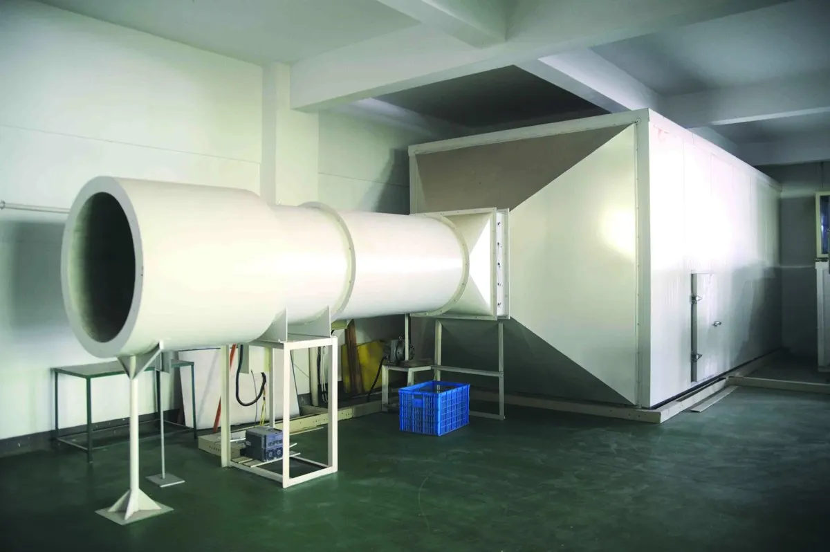
Check the airflow-pressure point on the exact model curve with voltage, speed, air density, sound, controls, and installation configuration declared. A free-air CFM value or duct diameter cannot prove installed airflow. Include clean and loaded filters and other credible resistance states.
Finally, commission the installed system. Measure airflow with a suitable method, verify pressure relationships and direction, and record electrical input, sound, vibration, and control settings. If results differ from the calculation, inspect blocked grilles, dirty filters, closed dampers, leakage, poor inlet conditions, and missing make-up air before increasing fan speed. A complete calculator output should preserve the method, rate source, inputs and units, operating scenarios, pressure duty, and verification plan.
For a deeper next step, use the centrifugal fan curve guide to read the operating point and the EC fan selection checklist to organize voltage, control, sound and installation details before starting from a generic CFM table.