Why can an EC motor run cooler and potentially last longer than an induction-motor alternative? The useful answer is not that EC technology is always cool. In a permanent-magnet EC design, the rotor changes one important loss path while electronic commutation controls stator current, but total temperature still depends on every loss and every thermal boundary in the installed system.
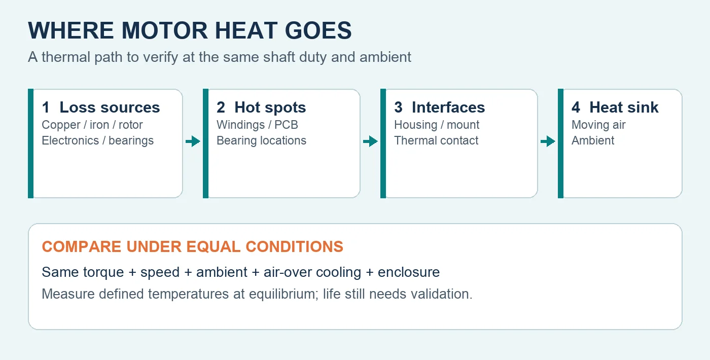
A fair comparison must hold shaft duty, speed, ambient conditions, airflow over the motor, mounting, enclosure, duty cycle, and measurement method constant. Lower temperature can create useful reliability margin, yet it cannot guarantee a specific service life by itself. This guide shows engineers and purchasing teams how to evaluate that claim with evidence.
Lock an Equal Motor Comparison
Compare motors at the same shaft power or torque and speed, with equivalent ambient temperature, air-over cooling, mounting, enclosure, electrical supply, duty cycle, and test method. A cooler housing photograph at a different load does not prove lower winding temperature or better installed efficiency.
Define the required operating range, not only a rated point. Include startup, normal load, reduced-speed operation, peak duty, repeated cycling, and the worst credible environment. Record the fan or machine load because blocked airflow, wheel friction, bearing condition, or a changed control command can move the motor operating point. If the terminology itself is unclear, the EC motor overview is useful background; it is not equal-condition thermal evidence.
Map Every Loss That Becomes Heat
Electrical input becomes shaft output plus losses. Relevant paths include stator copper loss, iron loss, rotor loss, electronic switching and conduction loss, bearing loss, and aerodynamic or mechanical loss. In an induction motor, rotor current produces rotor heating. A permanent-magnet rotor changes that path, but it does not eliminate stator, iron, electronics, bearing, or airflow-related heat.
Part-load behavior also matters. Electronic commutation and speed control can reduce input when the application needs less output, but switching strategy, motor efficiency, and cooling airflow change with speed. An air-over motor may receive less cooling at reduced fan speed even when electrical loss falls. The EC fan technology guide explains the architecture; the approval still needs measurements over the complete load-speed cycle rather than an assumption that part load is automatically coolest.
Follow the Complete Thermal Path
Heat must travel from windings and electronic components through internal interfaces, the housing, mounting structure, and moving air to the ambient environment. Thermal resistance at one interface can dominate the result. Dust, restricted airflow, recirculated hot air, a warm enclosure, contamination, or poor mounting contact can make an efficient motor operate at a high temperature.
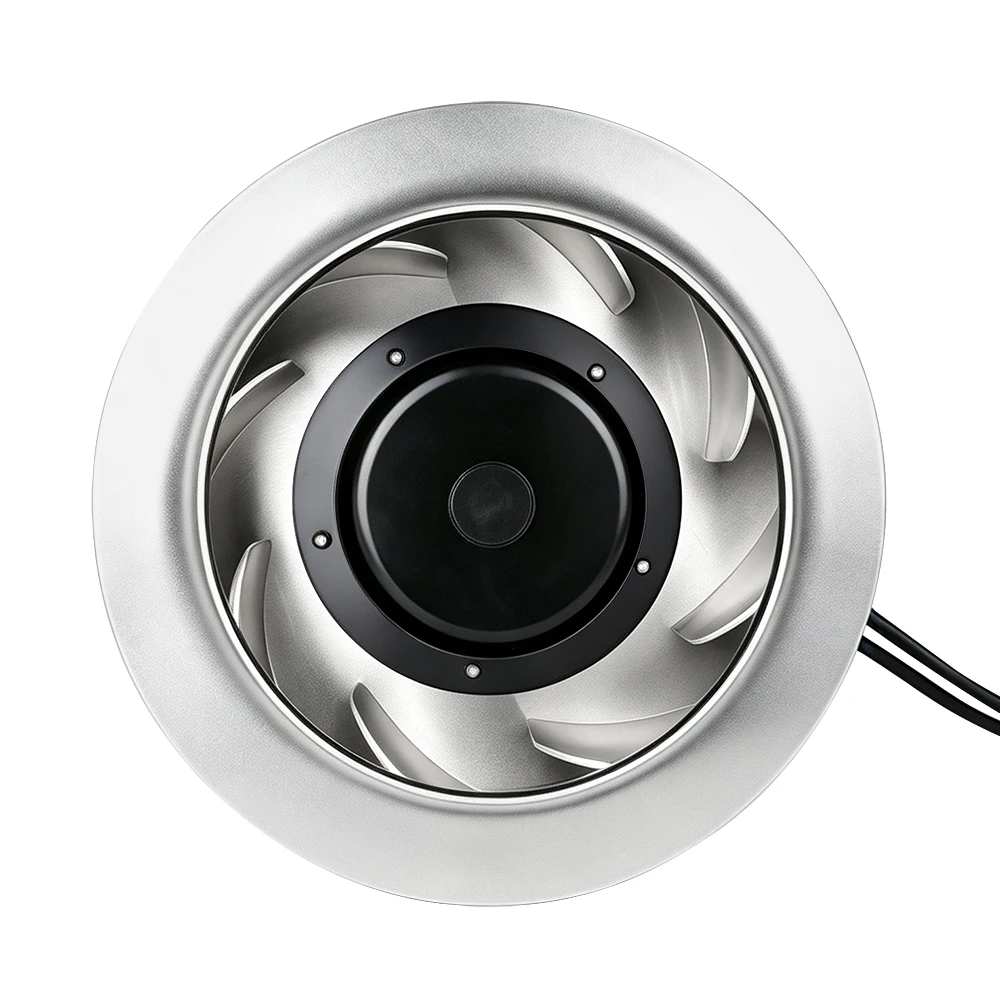
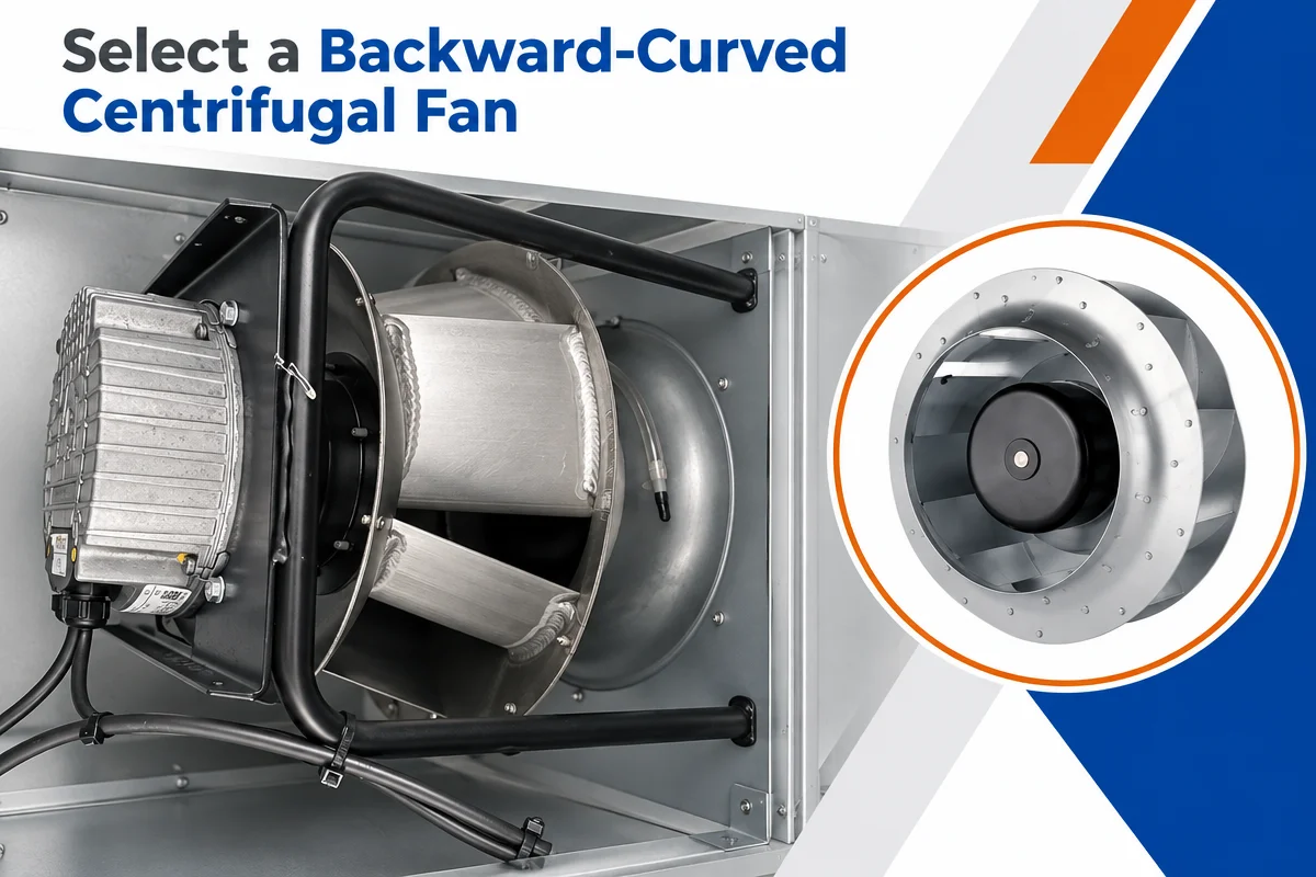
The pictured LONGWELL backward-curved assembly establishes visible product form only: inlet ring, blades, central cover, and exiting cable. It does not reveal the internal winding, rotor, controller, bearing condition, or thermal interfaces, and it provides no equal-condition temperature, efficiency, lifetime, compatibility, certification, or customer-performance evidence. The current EC backward-curved fan family is a sourcing route; exact-model thermal approval still requires its controlled documents and test record.
Name the Temperature and Protect the Process
The phrase runs cooler must identify what was measured. Housing temperature, winding average derived by resistance, embedded detector temperature, bearing temperature, and an electronics hotspot are different quantities. Use the method required by the exact product documentation, applicable acceptance plan, and project requirements, then wait for defined thermal equilibrium.
Temperature is one reliability stress among several. Insulation aging, bearing lubricant, electronic capacitors, solder joints, vibration, moisture, contamination, voltage transients, and start-stop cycles all contribute. Lower temperature can improve thermal margin, but a lifetime claim needs validated design data and relevant field evidence.
Protection should address both motor risk and process duty. Define thermal sensing, current limiting, locked-rotor behavior, derating, alarms, shutdown, restart, and communication response. A controller may reduce torque or speed to protect electronics while the served process loses airflow or cooling, so critical systems need independent process supervision and an approved fallback.
Test to Equilibrium and Hand Over the Evidence
Run an equal-condition thermal test with qualified personnel following the exact product and electrical instructions. Record ambient and inlet-air temperature, shaft demand, speed, voltage, current, input power, airflow over the motor, enclosure and mounting condition, and temperature at defined points. Continue until the acceptance plan’s thermal-equilibrium criterion is reached.
Repeat testing across the real duty cycle, supply tolerance, reduced-speed states, repeated starts, and worst credible ambient and contamination conditions. Exercise thermal protection, derating, alarm, shutdown, and restart behavior. Confirm that any protective response also preserves the required process outcome or moves the system to its approved safe state.
A reviewable package should include the exact motor and fan model, shaft duty, speed range, ambient and airflow envelope, enclosure and mounting, load cycle, power quality, control mode, temperature limits and methods, protection logic, bearing and electronics requirements, contamination, service access, and lifetime target. That evidence determines whether an EC solution has more usable thermal margin without promising universal temperature or longevity.
Choose the right ec axial fan manufacturer & supplier
Longwell manufactures 152 ec axial fan manufacturer & suppliers in-house. Send airflow, static pressure and voltage — an engineer replies with a matching model, performance curve and price within one working day.