A noisy bearing, a hot motor or a sudden drop in airflow may look like a clear diagnosis. Usually it is only the first clue. Industrial fan symptoms overlap: a vibration problem can begin in the wheel, drive, structure or airflow, while an electrical alarm may reflect the connected system rather than a failed motor.
A better prevention plan starts with a fault tree. Group the possible failure paths, collect evidence under safe conditions, correct the verified cause and then confirm the fan in its real operating mode. The five categories below are a practical organizing method, not a universal ranking of which failures happen most often.
Start with the symptom, but do not stop there
Before naming a failed component, write down what changed and when. Note the commanded operating mode, speed, airflow and pressure indications, vibration, temperature, alarms, maintenance history and any recent change to ductwork, filters, dampers or controls. The useful question is not simply “What part is bad?” It is “Which possible causes fit all of the available evidence?”
Preserve that evidence before adjustment or disassembly changes the condition. Sensor identity, units, timestamps and calibration status matter. One phone recording or dashboard screenshot can help describe a symptom, but it cannot establish root cause by itself. Where rotating or electrical hazards are involved, isolate energy and confirm zero movement under the approved site procedure before inspection.
1. Bearing and lubrication problems need a baseline
Heat, noise and vibration around a bearing can arise from lubricant choice or quantity, contamination, water, installation fit, alignment, shaft load, electrical discharge, ambient conditions or storage history. That is why “the bearing is hot” is not a complete diagnosis. Adding grease without checking the equipment instructions can make matters worse.
Prevention is equipment-specific: use the specified bearing and lubricant, keep handling clean, follow the approved installation and relubrication method, and trend condition against a valid baseline. The broader preventive blower maintenance guide can help organize routine checks, but the fan and bearing documentation remains controlling. There is no single grease interval or temperature limit that fits every fan.
2. Imbalance, vibration and looseness share symptoms
Deposits, erosion, corrosion, missing material, a bent or cracked wheel, rubbing, loose supports, misalignment, resonance, belt issues and aerodynamic excitation can all produce vibration. A balancing machine can correct a verified balance condition; it cannot make a damaged wheel, shaft or support structure sound.
Under safe isolation, inspect integrity and preserve the as-found condition before adding weights or replacing parts. Compare measurements by location, direction, speed and operating mode, then relate them to the machine history. The centrifugal fan balancing article provides useful context for that work, but balancing should follow inspection and a qualified diagnosis—not replace them.
3. Belts, pulleys and couplings fail as a system
Slip, heat or vibration in a driven fan may involve wear, contamination, alignment, tension, fasteners, pulley condition, coupling condition or guard interference. Inspecting one belt while ignoring the sheaves and shaft alignment leaves much of the drive path unchecked. On multi-belt arrangements, the applicable manufacturer procedure may also require a matched set and a defined tensioning sequence.
Guards stay installed during operation. Adjustment and close inspection require complete isolation and zero movement, with exact alignment and tension values taken from the fan and drive documentation. A direct-drive and belt-drive fan comparison can clarify the service differences between arrangements; it does not supply a universal setting for a particular drive.
4. Motor, EC, VFD and electrical faults need qualified evidence
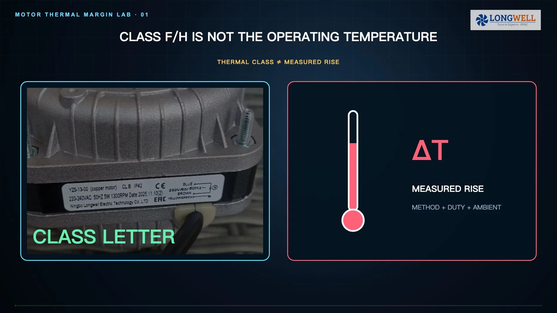
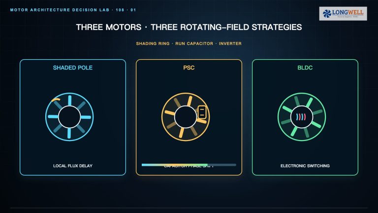
Supply voltage and phase, overload, connections, insulation, cooling, start frequency, harmonics, bearing current, drive parameters, motor-drive compatibility, sensors and electronics may all contribute to an electrical symptom. Current alone is neither a root cause nor a complete measure of real input power.
Electrical diagnosis and energized work belong to qualified people using suitable instruments, PPE and an approved program. A stop command or software “Off” state is not energy isolation; stored energy and automatic restart still have to be addressed. Prevention therefore includes correct application review, protection, cooling, parameter control, connection checks and an escalation path for recurring trips.
5. Airflow, the connected system and controls can mimic hardware failure
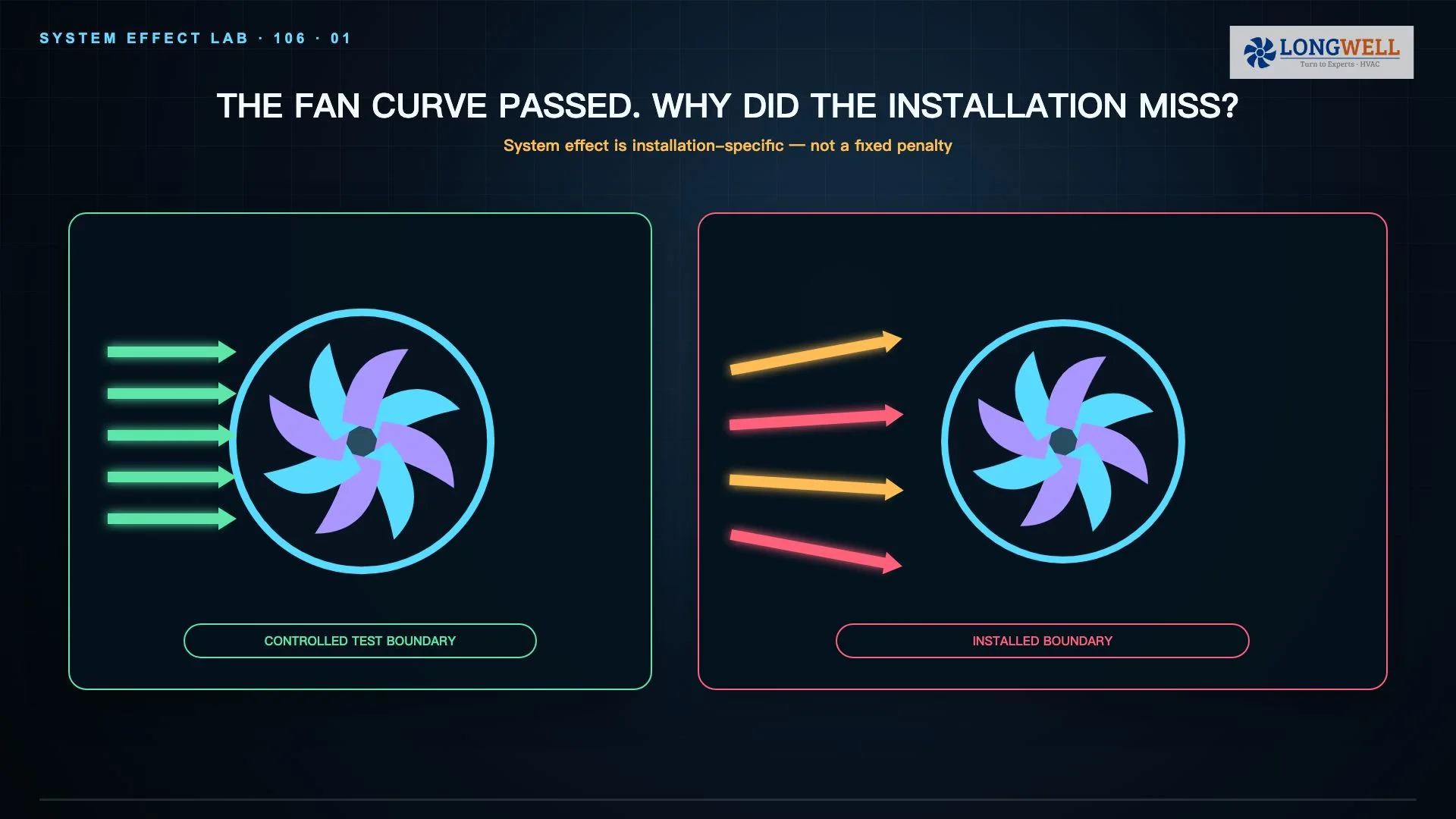
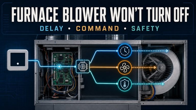
A restriction, dirty filter or coil, poor inlet or outlet condition, swirl, wrong rotation, closed damper, leakage, changed system resistance, unstable operation, backflow, failed sensor or sequence error can cause low airflow, noise, vibration or overload. Raising speed before understanding that condition can move the machine farther from its intended operating range.
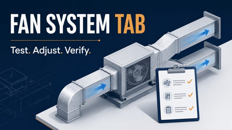
Confirm the actual operating mode with synchronized evidence: airflow and pressure, speed, real input power, vibration, temperature, alarms, damper position, sensor validity and the relevant fan and system curves. Look beyond the fan casing. The initiating cause may sit upstream, downstream or in a control sequence, while the fan shows only the consequence.

A practical fault tree moves from symptom to possible causes, then to safe evidence and verified prevention. It is not a one-symptom, one-part diagnosis.
Capture evidence before choosing the repair
A useful work record separates the symptom, possible causes, evidence and corrective action. Record the as-found state, operating mode, alarms and relevant measurements; then document what changed during inspection or repair. Failed parts, settings and maintenance history may be important when the initiating cause is not obvious.
This discipline prevents secondary damage from being mistaken for the original failure. It also makes escalation more efficient: a qualified technician or engineer receives a coherent sequence rather than a collection of disconnected observations. Alarm resets should be governed too. Repeatedly clearing a protective trip without correcting its cause removes evidence and may increase risk.
Prevention ends with a controlled return to service
Good prevention combines correct selection and installation with clean flow paths, secure supports, suitable clearances, maintained drives, approved lubrication, electrical protection, validated sensors and condition trends. The exact tasks and limits come from the equipment documentation and the site maintenance program, not from a generic run-hour rule.
After work, verify that tools and foreign objects are removed, fasteners and clearances are correct, lubrication is complete, guards are restored and personnel are clear. Then use the approved restart and monitored-run procedure to check vibration, temperature, airflow and pressure, speed, power, controls and alarms. Closing the loop matters: a repaired component is not the same thing as a verified machine.