A vibrating centrifugal fan does not automatically need a balance weight. A safe balancing job first proves that rotor unbalance is the repeatable fault, then uses a controlled measurement-and-correction loop. That distinction matters because balancing cannot repair a loose base, damaged bearing, bent shaft, rubbing component, alignment error, or structural resonance.
This guide is for maintenance engineers and factory teams reviewing a professional fan-balancing workflow. The practical decision is whether the evidence is stable enough to proceed, what controlled correction process applies, and what must be verified before the rotor returns to service. Trained personnel must use equipment, guarding, procedures, and acceptance criteria approved for the specific rotor and fan.
Confirm that unbalance is the repeatable fault
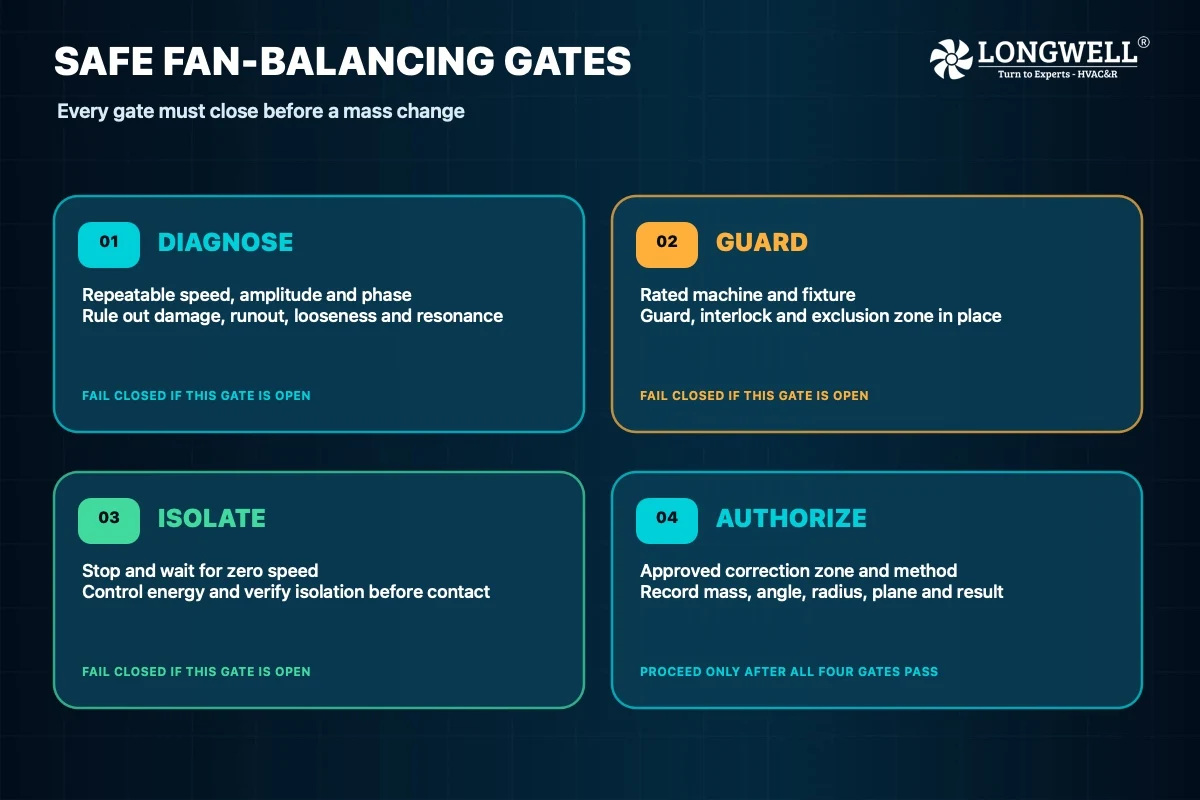
Collect vibration evidence under stable, repeatable operating conditions before changing the rotor. A speed-synchronous component with repeatable phase can support an unbalance diagnosis, but a single amplitude reading cannot establish the cause. Record speed, amplitude, phase, measurement position, operating condition, and run-to-run repeatability.
Inspect the impeller for contamination, foreign material, erosion, distortion, cracks, loose parts, and visible runout. Check the shaft, bearings, coupling, fasteners, base, and nearby clearances. Look for rubbing and consider whether operating speed is close to a structural resonance. If amplitude or phase changes unpredictably between comparable runs, stop and resolve the instability before adding mass. This diagnostic boundary also keeps rotor work separate from later centrifugal fan noise controls that address acoustic and installation paths.
Establish the safety boundary and freeze the configuration
Rotating components and temporary or permanent masses can become projectiles. Use a balancing machine, fixture, guard, interlock, and speed range rated for the rotor. Establish the required exclusion zone and follow the site’s authorization and emergency procedures. Before contact or any mass change, stop the machine, wait for zero speed, isolate it against unintended startup, and verify the isolation. Never reach through a guard or adjust a coasting rotor.
Clean the impeller and define its final test configuration before taking the baseline. Record rotor identity, hub and fastener condition, key or adapter state, rotation direction, fixture, selected balance speed, available correction planes and radii, and acceptance basis. A later change in mounting, hardware, contamination, or adapter position can invalidate the result. Blade form and width may inform the plan, but this centrifugal impeller geometry comparison is context rather than permission to choose a balance method by appearance alone.
Choose the specified plane strategy and capture a baseline vector
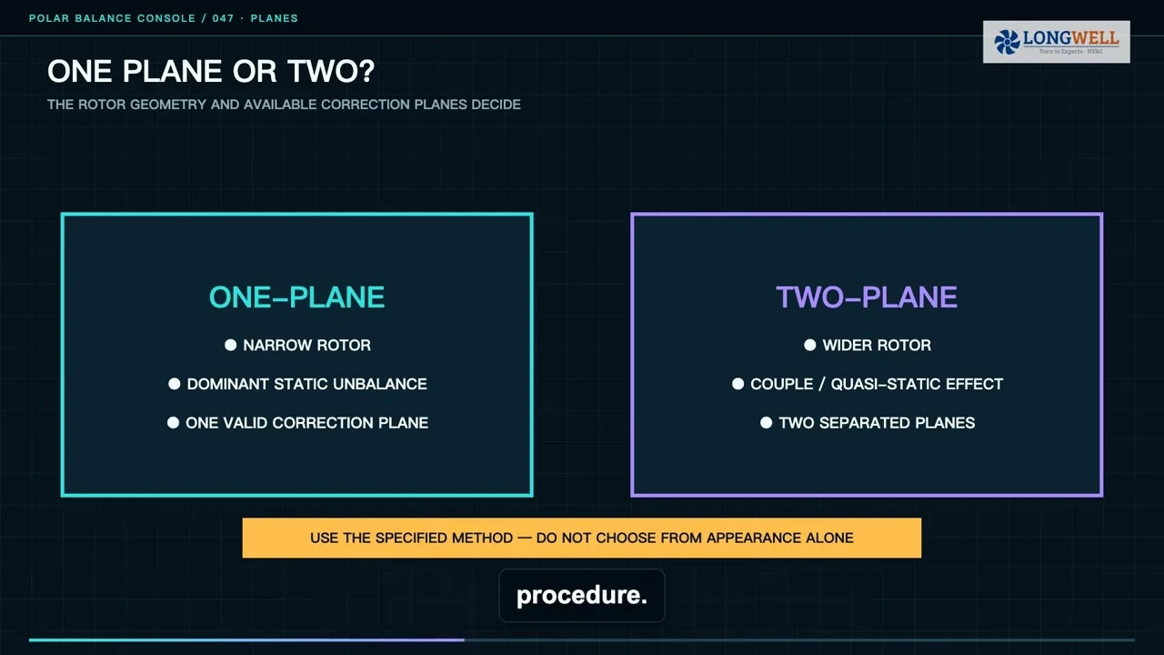
One-plane or two-plane balancing depends on rotor behavior, geometry, available correction locations, and the governing procedure. Some narrow, rigid rotors may be addressed in one plane; wider rotors may show couple or quasi-static behavior that requires two separated planes. Large size or an industrial label does not by itself make two-plane balancing mandatory.
Establish consistent measurement points and an angular reference, then capture baseline vibration amplitude and phase at the selected speed and condition. Together, amplitude and phase form a vector describing the current response. Without that reference, a team cannot determine how a known trial influence changed the rotor. Values visible on a balance-station display belong to that test and are not universal acceptance limits.
Use a controlled trial influence and an authorized correction
The governing procedure selects a known trial mass, angle, radius, and plane that are safe for the rotor, machine, and test speed. Secure it using an approved method, restore the guard, and repeat the run under the same conditions. The difference between the trial and baseline vectors is the rotor’s measured influence. Remove or retain the trial mass exactly as the procedure requires before applying the correction.
Keep correction mass, angular position, radius, and plane linked in one record. The same mass at a different radius creates a different correction effect. Add or remove material only in locations and by methods approved by the rotor manufacturer or qualified engineering authority. The method must protect structural strength, fatigue life, corrosion protection, and operating clearance. Improvised holes, unqualified welding, loose clips, or unsecured weights are not substitutes for an engineered correction.

Verify residual unbalance under the same test boundary
After correction, repeat the measurement with the same fixture, sensor positions, angular reference, speed, and operating condition. Evaluate residual unbalance against the agreed rotor or fan requirement. A smaller display value is useful evidence, but it is not by itself proof of acceptance. The applicable requirement and procedure—not a generic vibration number—define the decision.
Close the rotor job with a traceable record: identity, baseline vector, trial mass and location, correction map, final vector, fixture, speed, configuration, instruments, and acceptance basis. Record deviations and approvals as well. This evidence makes the result reviewable and gives future troubleshooting a reliable starting point.
Separate rotor balance from installed-fan vibration
A balance-machine result and installed-fan vibration are related but different. Once assembled, the response can also reflect shaft and coupling condition, bearing condition, alignment, mounting stiffness, fasteners, airflow, rubbing, and resonance. System resistance can move the operating condition, so review how a centrifugal fan develops pressure when airflow interaction changes the field result.
Commission the assembled machine under its authorized procedure instead of assuming that a rotor pass guarantees acceptable field behavior. The completed evidence chain should explain both decisions: why the rotor correction was accepted and why the installed fan is fit to return to its intended operating boundary.
Choose the right centrifugal fan
Longwell manufactures 1,121 centrifugal fans in-house. Send airflow, static pressure and voltage — an engineer replies with a matching model, performance curve and price within one working day.