A guard, a limit, and a signal
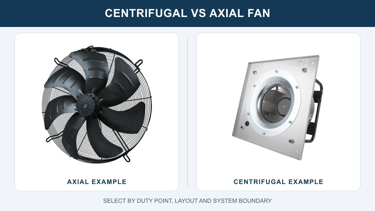
An OEM wanted their existing 200mm axial fan updated with a protective basket guard for a human-safe commercial cooling application. Alongside it, the specification asked for a fan tachometer output: a 4-pulse-per-revolution speed signal.
That second request says something about how the equipment is run. In short, somebody intends to watch these fans, not just power them.
The constraints
- First, at least 1200 m3/h through the new guard, on 220 V mains with no external transformer.
- Next, 110mm total depth including the curved steel guard, inside a 336mm frame.
- Meanwhile -25C to +60C ambient with IP44, for condensation and dust in equipment racks.
- Finally, 0-10 VDC control, EN 60335-1 compliance, and plug-and-play integration.
Why monitoring belongs in this specification
A cooling fan in an equipment rack fails silently. Meanwhile the rack keeps running, temperatures climb slowly, and the first visible symptom is downstream damage.
A fan tachometer output changes that. The controller sees RPM sag or stop the moment it happens, which converts a slow thermal incident into an immediate alarm.
What a fan tachometer output does
First came the guard, and it cost what guards always cost. Its steel rings add drag, so testing showed the original 50 W motor dropping well below the 1200 m3/h target once the guard went on.
Recovering the airflow
Bolting the guard onto the existing motor was tested and abandoned. Instead we upgraded the stator and rotor to an 80 W EC configuration in the same 200mm footprint.
Moreover, the EC choice was not only about watts. The customer control loop runs on 0-10 VDC, which the integrated electronics accept directly, and an AC induction motor in this class could offer neither the efficiency nor the interface.
What the tachometer output actually is
Inside an EC motor, the electronics already know the rotor position at every instant, because that is how commutation works. The fan tachometer output simply brings that knowledge out on a wire.
So four pulses per revolution means the controller counts pulse frequency and divides by four for RPM. At 3000 RPM, for instance, the signal runs at 200 Hz, fast enough to catch a stall in a fraction of a second.
What the signal makes possible
With RPM visible, the system can do more than alarm on a dead fan. For example, it can spot a slowing fan, which usually means a bearing on its way out or a filter loading up.
As a result, maintenance moves from schedule-based to condition-based. The fan gets changed because it is degrading, not because a calendar says so.
The rest of the build
Finally, the guarded assembly holds IP44 and the full -25C to +60C range, and delivers 1792 m3/h, comfortably clear of the 1200 m3/h floor.
Safety requirements for this class are published by the IEC as IEC 60335-1.
Technical Specifications
The quiet line in this table is the tachometer output. It is the only row that tells you about the fan after it ships.
| Parameter | Specification |
|---|---|
| Nominal Voltage | 230 VAC (Range 184~270 VAC) |
| Frequency | 50/60 Hz |
| Speed | 2650 ±5% rpm |
| Current | 0.6 ±10% A |
| Power Input | 80 ±10% W |
| Air Flow (Max) | 1792 m³/h / 1054 CFM |
| Static Pressure (Max) | 233 Pa |
| Noise Level | 61 ±5% dB(A) |
| Max Ambient Temp | 60 °C |
| Min Ambient Temp | -25 °C |
| Insulation Class | Class B |
| Protection Type | IP44 |
| Work System | S1 |
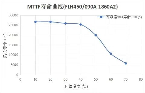
| Life Expectance | 50,000 Hours (L10 at 40°C) |
| Speed Control | 0~10VDC / PWM (1K-10KHz) |
| Impeller Material | Galvanized steel sheet |
| Bearings | Maintenance-free deep groove ball bearings |
| Total Depth | 110 mm (95±1.5 + 15 mm) |
| Outer Guard Diameter | 336 mm |
| Certifications | CE, RoHS, Reach |
Technical Documentation
View original customer requirement notes (DOCX). OEM procurement managers can review this initial input document detailing the base 1200 m³/h target.
Get final engineering specification sheet (PDF). HVAC engineers use this file to extract the exact P-Q performance curves, wire color coding, and dimensional schematics for the LWAE3G200ST-7PEW-17-00.

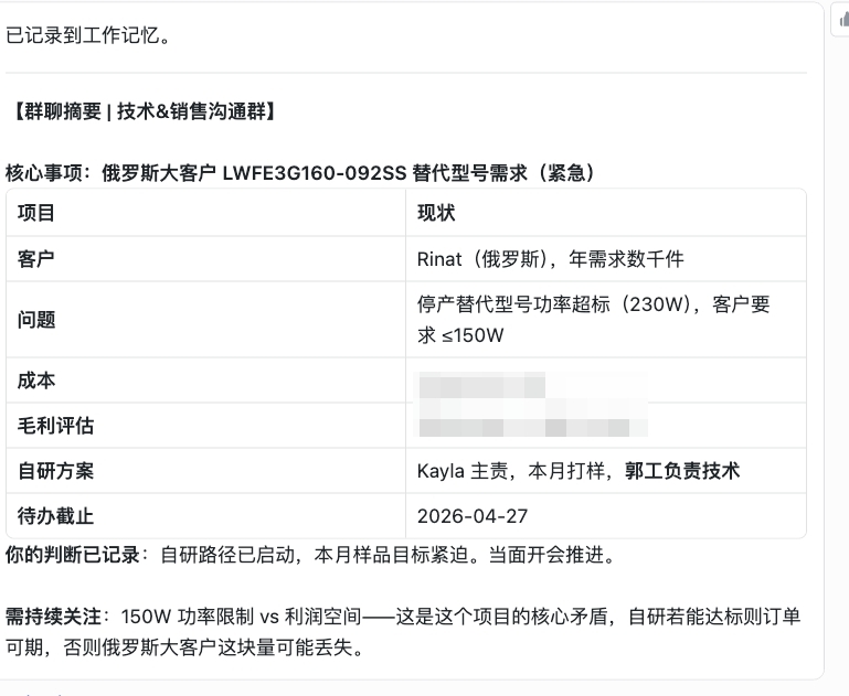
The internal project dashboard image captures the original PKW model specs, showing the 50W power consumption and 62 dB noise constraints.
Using a tach signal properly
A fan tachometer output is cheap to specify and easy to waste. Four points make it useful.
- Actually connect it. The commonest fate of a fan tachometer output is a cut wire. If the specification includes the signal, route it to something that reads it, alarms on it, and logs it, or the money bought nothing.
- Know the pulse count before you divide. Fans ship with 1, 2 or 4 pulses per revolution. A controller assuming the wrong count reads double or half speed, and both errors look plausible on a dashboard.
- Alarm on sag, not just on zero. A fan at 60% speed still makes a signal and still fails to cool. Set the threshold against the RPM your airflow calculation needs, not against stopped.
- Prefer motor-derived signals to add-on sensors. An EC motor reports its real electrical rotation. An external sensor adds a part, a mounting and a failure mode to measure what the motor already knows.
See our axial fans range, the EC axial fans section, or compact axial fans.
Questions about tachometer outputs
What does a 4-pulse tachometer signal look like electrically?
A square wave whose frequency is four times the rotation rate, usually an open-collector output that the controller pulls up to its own logic voltage. At 3000 RPM that is a 200 Hz square wave. Check the datasheet for maximum pull-up voltage and current before wiring it.
Can I retrofit a tachometer output to a fan that lacks one?
Externally, yes, with an optical or Hall sensor watching the blades. However, you are adding hardware to obtain what an EC motor gives away free. If monitoring matters to the design, it is cleaner to specify a fan with the output built in.
Why would a fan slow down rather than stop?
Rising bearing friction, a loading filter, falling supply voltage, or increasing system resistance all drag speed down before anything fails outright. That drift is exactly the early warning a speed signal exists to catch.
Is the tachometer the same as speed control?
No, they travel in opposite directions. The 0-10V input tells the fan how fast to run; the tachometer output reports how fast it actually runs. A robust system uses both, commanding a speed and verifying it happened.
Technical Documentation & Resources
Got a duty point you need matched?
Tell us the airflow, the pressure and the space you have. Then we mark your duty point on a tested curve and send the drawing back. Meanwhile samples and custom spec sheets take up to 90 days. Since 1990 we have supplied OEMs across HVAC, refrigeration and industry.
Browse Related Products:
🏆 ISO 9001 / ISO 14001 / ISO 45001 | CE (TÜV) | UL/ETL | ATEX Zone 21/22 | AMCA 210/211 / ISO 5801 tested
Choose the right axial fan
Longwell manufactures 1,086 axial fans in-house. Send airflow, static pressure and voltage — an engineer replies with a matching model, performance curve and price within one working day.