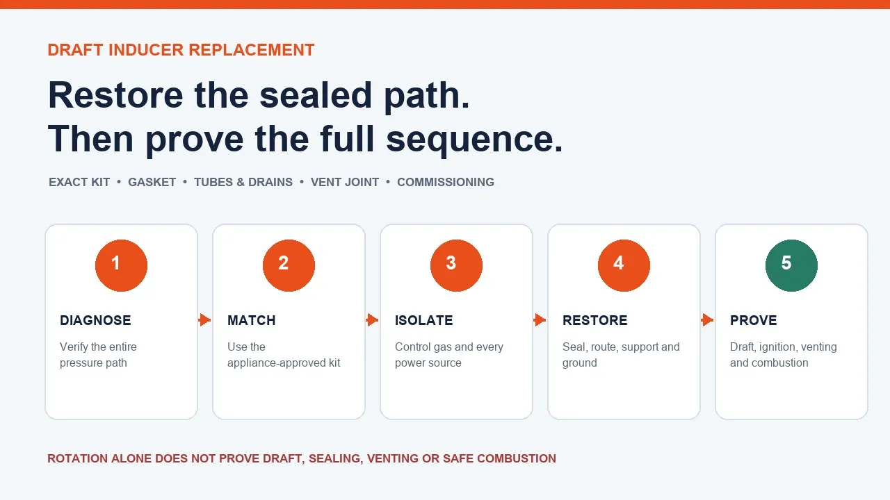
Replacing a draft inducer motor is a sealed combustion-path repair, not a generic fan-motor swap. The correct result is an approved assembly that establishes the furnace’s specified draft, keeps the vent and condensate paths intact, and allows every safeguard to complete the intended ignition sequence. A new motor that merely rotates is not an accepted repair.
This guide is written for qualified HVAC service personnel and for owners preparing an informed service call. Gas-furnace diagnosis, energized measurements, pressure testing, gas work, combustion analysis, and carbon-monoxide testing require the exact appliance literature, suitable instruments, local-code compliance, and a licensed professional. Never bypass a pressure switch, rollout switch, limit, flame safeguard, or door interlock.
Why the Inducer Is Part of the Combustion Safety Sequence
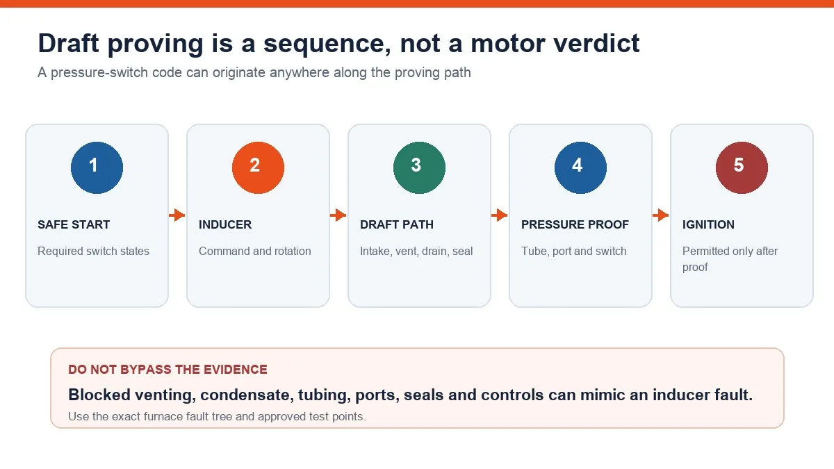
On a heat request, the control first checks the required starting states. It commands the inducer, then looks for the draft condition through the pressure-proving circuit. Only after that proof does the control allow ignition and fuel flow. Flame must then be proved, and the inducer normally continues through the heating cycle and a defined post-purge.
That sequence gives a pressure-switch fault diagnostic value, but it does not identify the failed component by itself. A restricted intake or vent, blocked termination, condensate backup, damaged tube, obstructed pickup port, collector-box leak, weak electrical connection, wheel damage, control fault, or heat-exchanger restriction can prevent proof. Changing the motor without resolving the complete path can leave the original unsafe condition in place.
Confirm the Fault Before Ordering an Assembly
Start with the furnace model and serial number, fuel and staging configuration, installation orientation, fault history, and the exact manufacturer’s service tree. A qualified technician should examine the intake and vent where fitted, condensate trap and drains on condensing equipment, pressure tubes and ports, electrical connections, wheel and housing, and accessible sealing interfaces.
Live voltage, current, and pressure evidence must come from approved test points under the furnace service procedure. A motor command with no response, abnormal mechanical condition, and model-specific electrical evidence may support an inducer diagnosis; a code alone does not. If the evidence conflicts, stop and resolve the conflict before buying a part.
Build a Model-Specific Replacement Passport
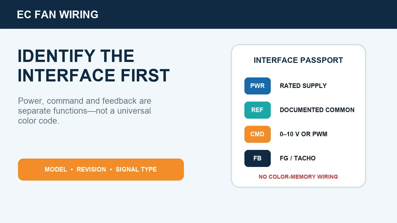
Use the furnace parts record and approved kit instructions to identify the complete assembly. Capture the appliance identity, original inducer and kit numbers, supply and stage or speed function, wheel and housing geometry, rotation, harness and protective ground, pressure-port arrangement, exhaust connection, condensate orientation, mounting pattern, gasket, thermal devices, and permitted furnace positions. A similar housing or motor rating is not proof of equivalence.
For background, this centrifugal fan guide explains basic impeller and housing roles, and this air-pressure overview shows why geometry and the connected system affect pressure generation. These are general engineering references, not furnace parts authority. Appliance approval and kit instructions control the repair.
Before removal, create a connection map with photographs and labels for the power harness, separate ground, every pressure tube and port, condensate routing, exhaust fitting, thermal devices, fasteners, supports, and assembly orientation. The record prevents hose color or memory from becoming the reassembly method.
Establish the Professional Safety Boundary
Follow the appliance shutdown procedure, control the gas supply as required, disconnect every electrical source, apply the applicable lockout or tagout process, control stored energy, and verify de-energization. Some installations have more than one source or service switch. Allow hot components to cool, protect against sharp sheet metal, and keep condensate away from controls.
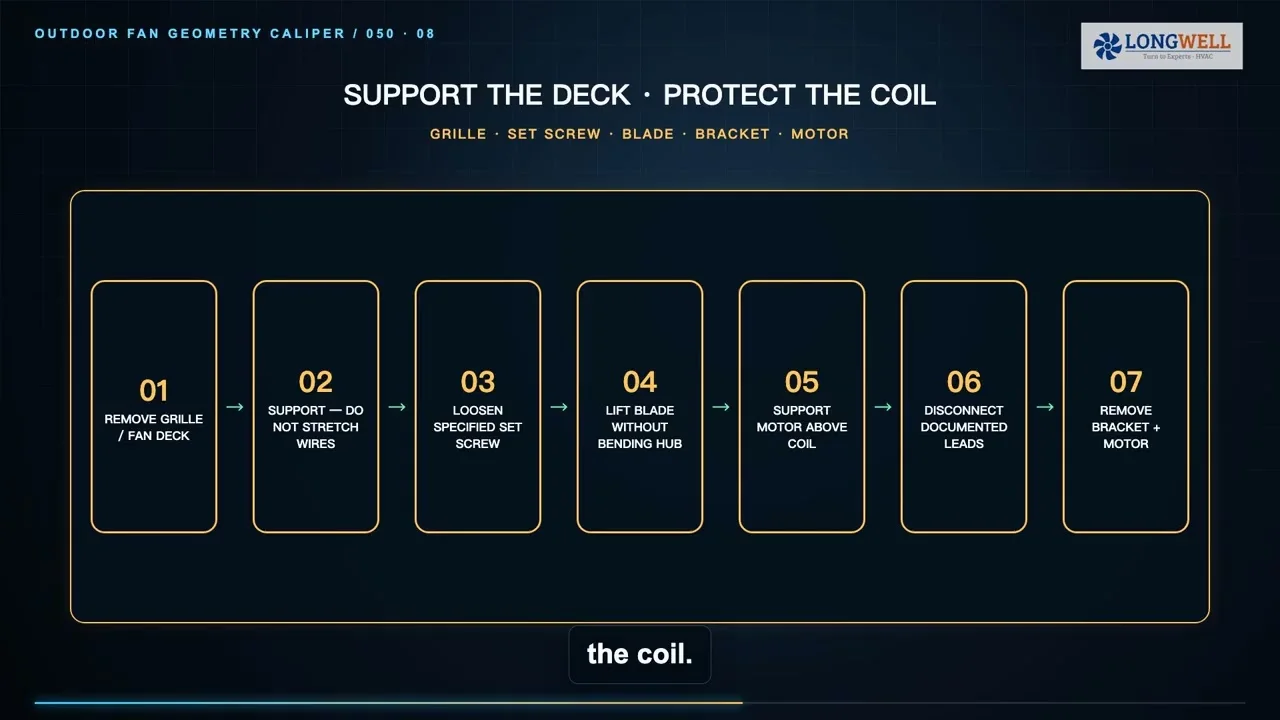
The model-specific instructions decide the removal order. Nearby vent, drain, and tubing connections need support so they are not cracked or distorted. Do not pry against the heat exchanger, deform a mating surface, or improvise an energized access method to speed the work.
Restore Every Sealed and Sensing Interface
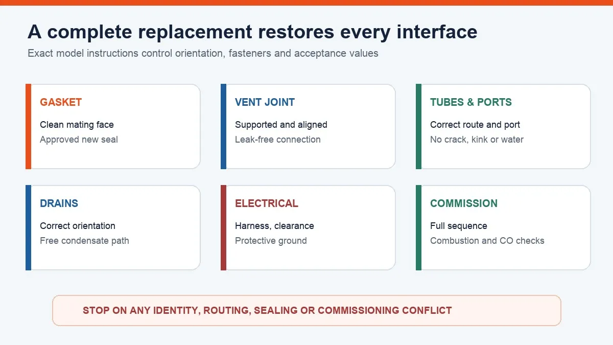
Remove old gasket material only by the approved method and without damaging the mating surface. Fit the specified new gasket in its stated orientation and locate the approved assembly correctly. Fastener type, sequence, and torque are kit-specific; there is no universal inducer torque or acceptable “snug” standard.
Restore the exhaust joint so it is aligned, supported, and leak-free. Return condensate components to the arrangement required for the furnace position. Connect every pressure tube to its documented port without cracks, kinks, sags, trapped water, or blocked pickups. Restore the harness, protective ground, clearances, and any thermal device exactly as recorded. Do not adjust or substitute a pressure switch to make it agree with the new assembly.
Commission the Full Furnace Sequence
Before startup, inspect the complete gasket perimeter, vent joint, drains, tubes, wiring clearance, ground, fasteners, supports, and accessible wheel path. Remove tools and temporary controls, clear the work area, and reinstall every required panel and guard.
The authorized startup must verify inducer operation, stable draft proof, ignition, flame proof, heating, post-purge, and condensate drainage without abnormal rubbing, vibration, leakage, or short cycling. Acceptance also requires comparison with the model’s pressure and electrical data, inspection of vent and collector-box integrity, and the combustion and carbon-monoxide checks required by the manufacturer and local rules.
If draft still fails, stop. Return to the vent, intake, condensate, tubes, ports, sealed joints, heat exchanger, installation, electrical supply, and control evidence. Close the job only with a service record containing the appliance and kit identity, connection map, gasket and routing checks, measured results, and the exact acceptance basis. A complete inducer replacement ends with proven safe operation, not with visible rotation.