A paint booth can show an acceptable average airflow while overspray remains trapped behind a vehicle, workpiece, or operator. That hidden recirculation can affect finish quality, overload one collector zone, and leave vapour, mist, or combustible residue where the ventilation system was expected to sweep contaminants toward the exhaust.
Fan selection must therefore begin with the coating process and the complete booth airflow field. Supply air, booth geometry, the part, overspray collectors, loaded filters, exhaust duct, treatment, discharge, make-up air, controls, and fire protection operate as one system. This guide gives coating, automotive repair, and industrial teams a practical framework for defining installed duty without making unsupported safety or certification claims.
Define the Coating and Process Before the Fan
Identify the coating and cleaner from their safety data sheets, then document application rate, solvent or water content, liquid or powder process, electrostatic equipment, part size, conveyor movement, operator position, and any curing mode. These inputs establish the contaminant, residue, fire, explosion, and electrical design basis. A generic description such as paint booth is not enough to qualify hardware.
The applicable code edition, booth listing, environmental treatment, classified areas, and authority-having-jurisdiction decisions must also be identified for the project. Prescriptive values from one jurisdiction should not be presented as universal global rules. Qualified specialists must connect the exact chemistry and process to the required ventilation, electrical, grounding, and fire-protection provisions.
Choose and Map the Booth Airflow Strategy
A crossdraft booth moves supply air horizontally from the clean side toward an exhaust wall. A downdraft booth moves conditioned air from the ceiling toward a floor or low-level exhaust. Either arrangement can work when the booth, part, and spray process are engineered together; neither is automatically correct for every operation.
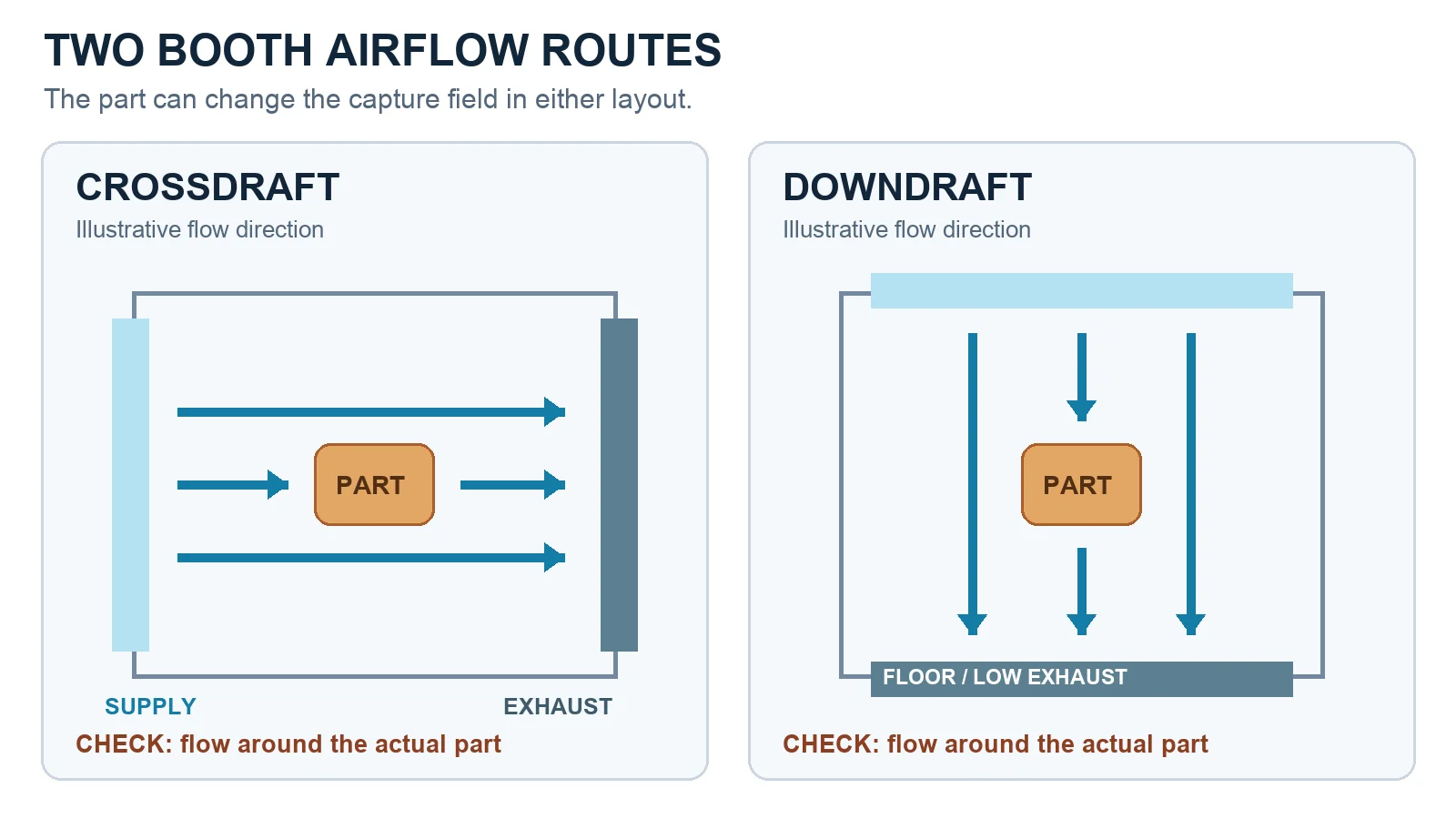
Map the entire booth rather than relying on one average reading. Supply plenums, diffusers, open doors, the part, operator movement, and blocked collector areas reshape the field. Look for reverse flow, dead pockets, and high-speed jets that disturb coating application. Test intended part positions and credible operating states, because a large workpiece placed near the exhaust can obstruct the collector and divert overspray.
Overspray needs a controlled route from the spray zone into the collector without bypass. Baffles, filter banks, and treatment devices must match the process, remain accessible for inspection and cleaning, and avoid creating concealed residue pockets. Uniform distribution is evidence that the path works; fan speed alone is not.
Select Against Clean and Loaded Resistance
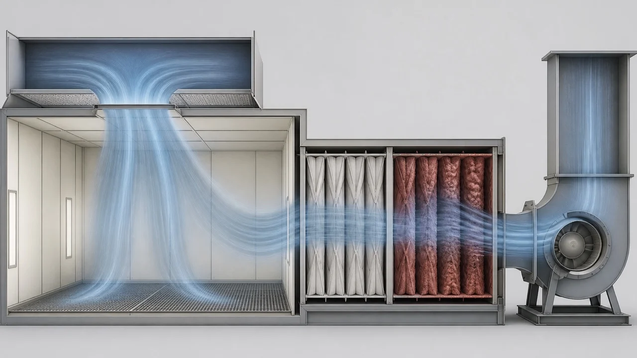
Build the full resistance path through the supply intake, conditioning section, booth opening, plenums, overspray collectors, exhaust duct, treatment equipment, and outdoor discharge. Plot clean and loaded system curves against the fan curve. The centrifugal fan-curve guide explains the operating-point method; it does not establish a booth duty. Select installed airflow, pressure, motor load, and control range at the project intersections rather than using a free-air catalog maximum.
As filters or collectors load, pressure loss rises and airflow distribution can change. One overloaded bank may pull the capture field sideways even though the fan remains on. Monitor the required airflow or pressure indication, inspect the full collector face, and define service limits from the approved booth instructions and process risk assessment. Recheck capture after maintenance so a replaced or incorrectly installed filter does not silently change the field.
Pass the Hazard and Interlock Gate
Hazard qualification cannot be reduced to the phrase explosion-proof fan. Coating chemistry, vapour or powder characteristics, classified area, fan construction, spark-resistance basis, motor and electrical location, grounding, residue compatibility, listing, and authority approval must agree as a package. Corrosion resistance is likewise a material-and-process decision, not an attribute that can be inferred from a generic fan image.
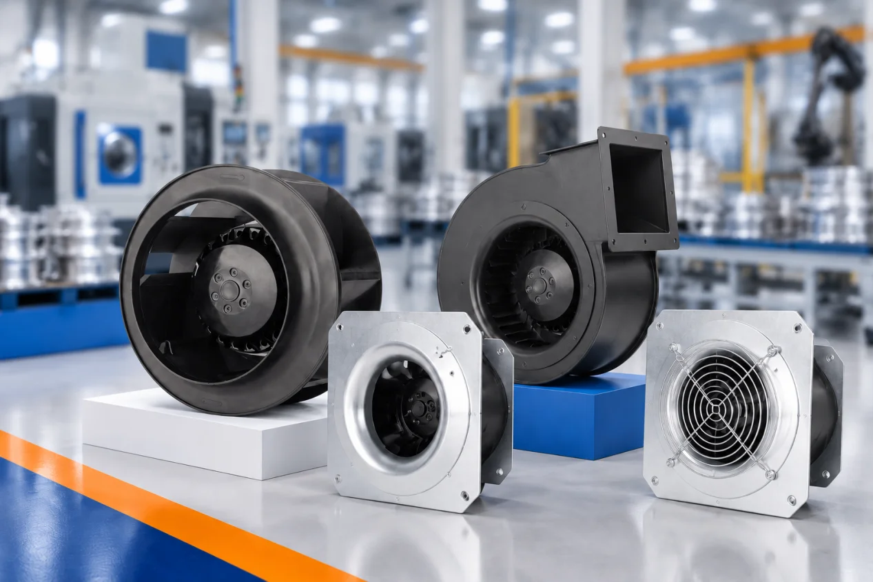
For family-level discovery only, review LONGWELL forward-curved centrifugal fans and backward-curved centrifugal fans as construction categories. These family pages do not qualify a model for spray exhaust, prove spark resistance or hazardous-area approval, or establish coating compatibility and installed duty. Request the exact model, revision, curve and applicable approval documents for the project.
Make-up air must replace exhaust without creating door jets, excessive turbulence, or contamination in adjacent work areas. Review booth and building pressure, supply-air temperature and distribution, nearby exhaust systems, and combustion equipment. Discharge and any proposed recirculation require separate qualified review under the applicable rules and treatment basis.
Interlocks should prove credible ventilation before spraying is enabled and stop the process when required airflow is lost. Coordinate fan status, airflow or pressure indication, collector alarm, spray equipment, conveyor, make-up air, grounding provisions, fire protection, and safe restart. A speed command or running motor does not prove that hazardous contaminants are controlled.
Commission the Actual Booth and Part Envelope
Commission the booth with the intended parts and operating states. Map airflow, observe overspray capture, record clean and loaded pressures, verify alarms and shutdowns, and inspect residue removal, access, grounding, discharge, and make-up air with qualified specialists. Include credible obstructions and collector loading rather than testing only an empty, clean booth.
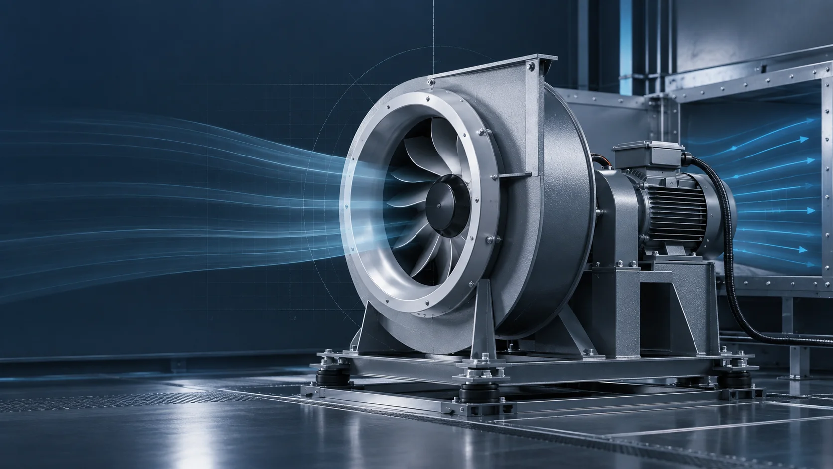
The available LONGWELL airflow-test-room image provides measurement context only. It is not a paint booth, spray installation, hazardous-area qualification, or proof of fan suitability. The animated airflow and overspray fields are explanatory diagrams, not computational validation or certification evidence.
A defensible project package should include coating safety data, process type and rate, part envelope, booth geometry, airflow basis, clean and loaded losses, filters and treatment, duct and discharge, make-up air, electrical classification, interlocks, fire protection, voltage, maintenance access, and acceptance tests. Final approval depends on that complete evidence set and the adopted project requirements.