A stuck blower wheel should be treated as an interface problem before it becomes a force problem. The useful question is not how hard to pull. It is whether every retainer has been identified, whether the load can pass through the hub, and whether the puller can stay coaxial with the shaft without bending the wheel or loading nearby parts.
This guide is for qualified fan and HVAC service personnel working from the exact equipment documentation and an approved hazardous-energy procedure. Blower-wheel designs differ, so the video is a visual decision aid rather than proof of a model-specific removal method, puller fit, direction, force, clearance, or replacement compatibility.
Lock out the equipment and preserve the as-found condition
Before contact with the wheel, isolate every hazardous energy source, control stored energy, and verify the isolated state with the method required for the equipment and site. Remove only the access parts authorized by the service procedure. Support any assembly whose weight or position could shift when the wheel releases.
Photograph the hub, shaft end, motor position, wheel position, inlet relationship, clearances, wiring route, and every visible retainer. Record the equipment model, serial number, wheel and motor identifiers, and document revision. These records matter because a previous repair, corrosion, distortion, or shifted wheel can make the current position a poor reassembly reference.
Confirm what is retaining the hub
Clean the visible interface only as permitted by the equipment instructions, then identify the actual retention arrangement. Look for set screws, keys, collars, nuts, clips, shoulders, or other model-specific features without assuming their number, thread direction, or removal order. A hidden or partially loosened retainer can turn a controlled pull into hub, shaft, bearing, or housing damage.
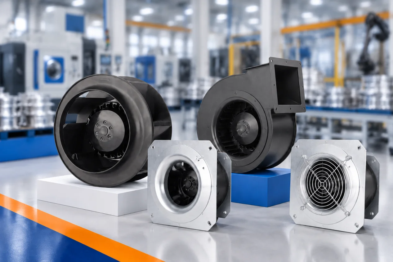
The LONGWELL blower wheel product family shows broad wheel forms, but it does not identify the interface in the equipment being serviced. Exact drawings, parts information, and the current manufacturer procedure remain the authority.
Decide whether a puller has a safe load path
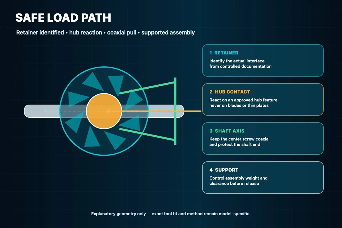
A puller is appropriate only when its reaction points can bear on the hub or another manufacturer-approved feature. Do not place pulling force on blades, rims, inlet cones, thin backplates, or an unsupported motor bracket. The center screw must remain aligned with the shaft axis, and its tip must protect rather than deform the shaft end or threads.
Check that the puller arms, crossbar, center screw, wheel, shaft, housing, and nearby components have clearance through the anticipated movement. If the tool cannot seat squarely, the hub has no stable reaction surface, or the assembly cannot be supported, stop and move the job to an approved fixture or service method. Tool size and geometry must come from the actual interface, not from a generic article.
Apply controlled load and watch the interface
Take up slack gradually while watching the hub, puller, shaft, wheel, motor support, and surrounding clearance. Keep the load coaxial and pause whenever the tool shifts or the wheel begins to distort. Progress is established by controlled relative movement at the hub, not by arm effort, sound, or a universal turn count.
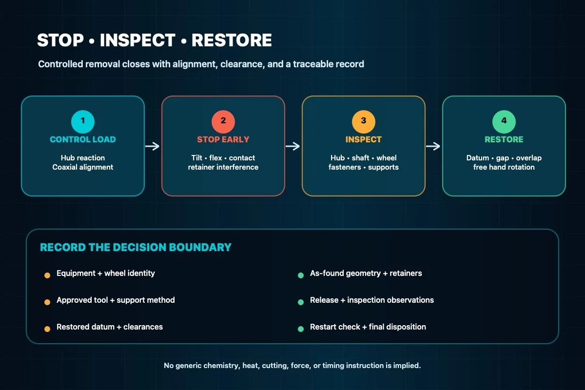
Stop on blade or backplate flex, hub distortion, puller tilt, shaft-end damage, retainer interference, bearing movement, housing contact, or loss of support. This guide does not authorize penetrating oil, a fixed soaking period, generic heating, impact, shaft cutting, or an uncontrolled force limit. Any additional treatment requires exact material, fire, electrical, sealing, bearing, and manufacturer boundaries for that assembly.
Inspect the parts after the wheel releases
Support the wheel as it comes free; do not let release energy drop or swing it into the housing. Inspect the hub bore, shaft, key or flat, retainers, threads, locking features, motor support, and wheel structure. Record corrosion, fretting, burrs, cracking, deformation, contact marks, or missing hardware. Cleaning and surface correction must follow the applicable instructions rather than an improvised abrasive or chemical treatment.
If the wheel, hub, shaft, or retainer is damaged or its identity is uncertain, quarantine the part for an engineering decision. A family resemblance or nominal diameter does not establish replacement equivalence.
Restore position, clearance, and free rotation
Reassemble with the specified orientation, datum, fasteners, locking features, and tightening method. Restore the documented wheel position, radial gap, inlet overlap, and clearance to the housing and guards. Before energization, use the approved manual check to confirm free rotation through a complete path with no rubbing, interference, or unexpected movement.
Then restore guards and access parts required for the planned test state. The site’s centrifugal fan maintenance reference provides broader operating context, but the exact equipment manual still governs inspection points and acceptance limits.
Restart under control and close the service record
Clear tools and personnel, authorize the test, and observe from the protected position defined by the procedure. Verify rotation direction, stable clearance, absence of contact or abnormal movement, and the equipment-specific checks required after service. Stop on a mismatch, rub, vibration change, alarm, or movement outside the approved boundary; do not continue running in hope that the assembly will settle.
Close the record with the equipment and part identities, as-found photographs, retainer arrangement, approved tool and support method, observations during release, inspection findings, reassembly datum, clearance and hand-rotation checks, restart result, technician, and date. When drawings or interface authority are missing, contact LONGWELL support with those records instead of guessing at a removal or replacement path.
Choose the right fan impeller
Longwell manufactures 10 fan impellers in-house. Send airflow, static pressure and voltage — an engineer replies with a matching model, performance curve and price within one working day.