Ask how much CFM per person a room needs and it is tempting to look for one reusable number. That shortcut misses the design problem. People are one source of outdoor-air demand, but area, occupancy type, distribution, system arrangement and the adopted method can all change the result.
The practical answer is a traceable path from the current design basis to zone outdoor airflow, system intake airflow and a fan duty that includes airflow and pressure.
Begin with the governing design basis
Ventilation work starts with the method that governs the project: the adopted edition, jurisdictional requirements, occupancy classification, owner criteria and project brief. A value copied from an old schedule or another building type may not belong to the current space.
Write the basis beside the calculation. Record the occupancy category, edition, approved design population and operating modes. This supports review without turning a general article into a substitute for the controlled standard or project engineer.
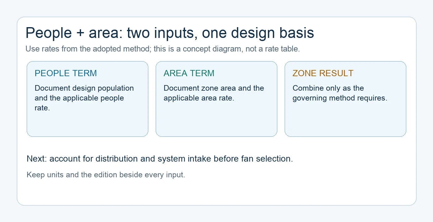
Combine the people term and the area term where the method requires it
Many non-residential methods combine a people-related term with an area-related term. The people term responds to design population, while the area term remains connected to zone floor area and use. Leaving either out can distort the result.
“CFM per person” is therefore one input to a wider calculation. Use definitions from the project’s current controlled source, not a generic copied table, and state how both terms enter the zone result.
Keep design population separate from sensed occupancy
Design population and sensed occupancy answer different questions. Design population is a documented input for the space. A sensor, booking system or schedule responds to use at a particular time. A transient signal should not silently replace the approved basis and its fallback logic.
Where demand-controlled ventilation is used, document the minimum condition, sensor locations, calibration, sequence, alarms and response to missing or implausible signals. The system still needs a defined fallback state.
Follow the air across every system boundary
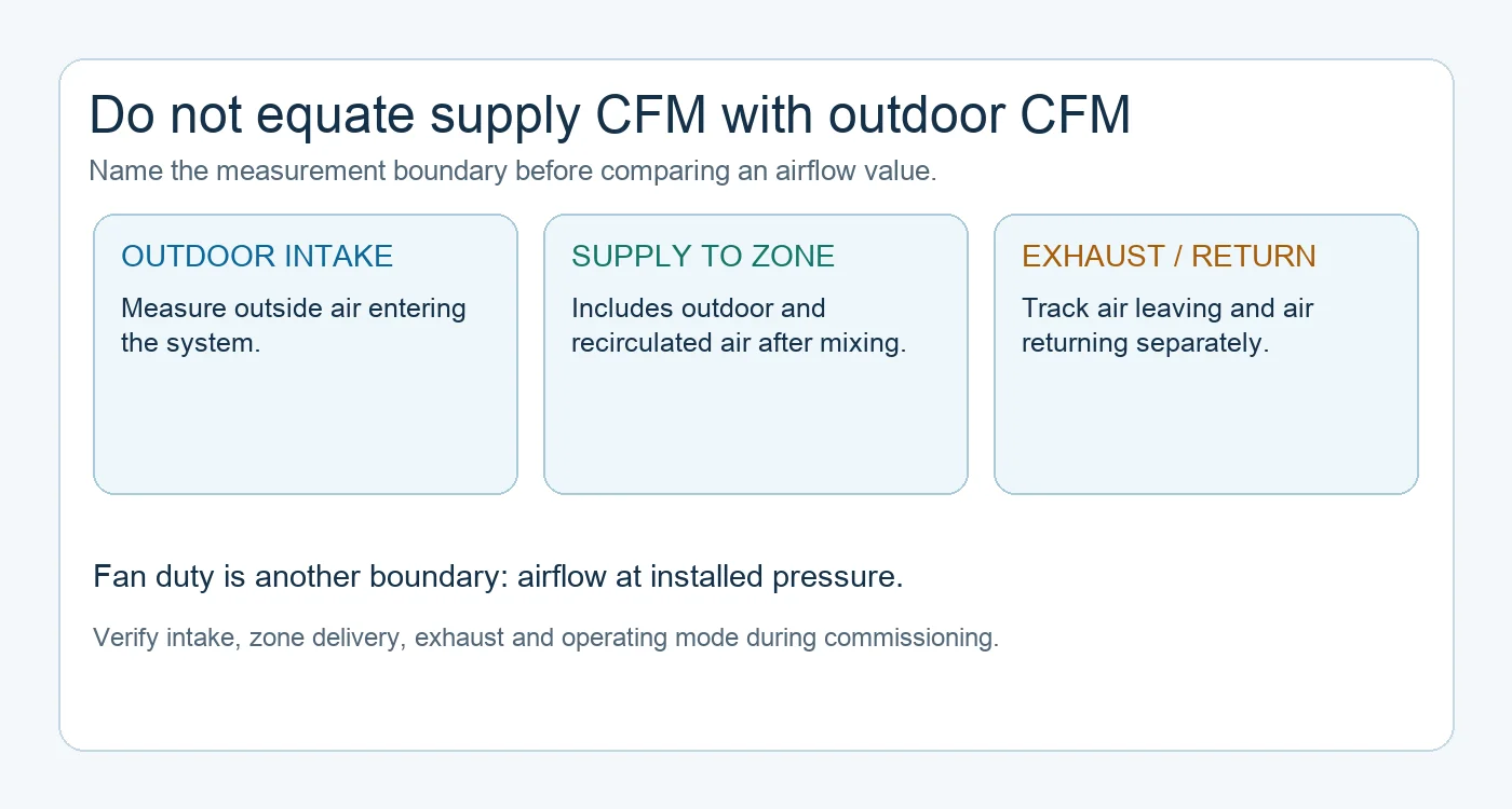
Outdoor, supply, recirculated and exhaust air are related but not interchangeable. Outdoor air enters from outside; supply air is delivered after mixing or treatment; recirculated air returns for reuse; exhaust air leaves the boundary. A free-air fan rating does not establish occupied-zone delivery.
Draw the path: intake, mixing point, treatment, supply, return, transfer and exhaust. Identify leakage, short-circuiting and modes that change the balance. Clear boundaries prevent supply air from being reported as outdoor air.
Account for distribution and multizone behavior
Airflow entering a zone is not automatically effective breathing-zone delivery. Diffusers, returns, operating mode, stratification, obstruction and short-circuiting can change distribution. The applicable method may require an adjustment rather than ideal mixing.
A multizone system adds another layer. Zone fractions, diversity, system ventilation efficiency, critical-zone behavior and control modes can make intake different from a simple sum. Keep the zone calculations visible and show how the selected method reaches the common intake.
Treat carbon-dioxide sensing as a control method, not a universal conversion
Carbon-dioxide measurement can support demand control when the sensing and sequence are appropriate. It is not a universal direct reading of required CFM per person. Outdoor concentration, generation assumptions, mixing, location, calibration and occupancy changes affect the signal.
Use the signal within an approved sequence with minimums, alarms and fallback behavior, then commission it across intended modes. One displayed concentration is not proof of outdoor airflow, zone delivery or compliance.
Use specialist methods for spaces outside the general case
Residential, healthcare, laboratory, hazardous-process, smoke-control and other special applications may follow dedicated criteria and risk controls. A general people-and-area explanation cannot replace those methods.
Name that boundary early and involve the qualified disciplines responsible for it. Avoid blending unrelated methods simply because they share an airflow unit.
Select the fan only after airflow and pressure are defined
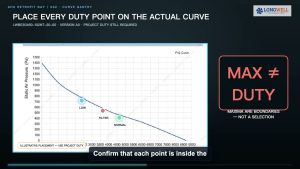
An airflow requirement is not a complete fan duty. The fan must operate against pressure from the real path, including ducts, fittings, filters, coils, dampers and terminals. Control range, sound, access, redundancy and operating modes may also shape the decision.
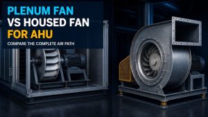
Once the arrangement and duty are documented, a guide to fan types for ventilation systems can help organize the next comparison. For one example of linking airflow to pressure, see the overview of axial fan performance, CFM and static pressure. The centrifugal fan family is a family-level starting point when the defined system resistance calls for comparing that construction. These pages are navigation context, not proof that a product fits the project or that a published example represents the installed system. Final selection requires current model information and the project’s verified operating boundary.
Close the loop with TAB and commissioning
Testing, adjusting and balancing turns design intent into field evidence. Confirm intake and exhaust paths, zone delivery, pressure relationships, modes and sequence response. Check sensors and labels as well as airflow.
Commissioning should record uncertainty and unresolved limits. If behavior does not match the basis, trace the difference through the air path before changing the fan or control setpoint. The result is a documented chain from adopted method to zone requirement, system intake, fan duty and field verification.