Choosing an EC fan for an air handling unit (AHU) retrofit starts with the existing system, not a replacement catalog picture. The useful question is: what airflow must the AHU deliver, against which pressure boundary, inside what available space, and with what electrical and control connections? Those answers determine whether a single EC plug fan, a small array or another construction is worth evaluating.
Practical decision: lock the required duty point and cabinet drawing first. Then ask for a current curve and drawing for the exact fan model and suffix. Use measured airflow during commissioning to check the completed installation.
Survey the present AHU and define the real duty
Record the required supply airflow and measure what the present unit delivers. Note the filter condition, coil condition, damper position and control setting at the time of each reading. A fan nameplate describes a component; it does not describe the pressure losses of an AHU that has been modified or maintained over years.
Measure pressure at identified points and state whether the selection target is fan static pressure, fan total pressure or pressure across a larger section of the unit. Record electrical input at the same operating state if an energy comparison is planned. Photograph the fan compartment, access door, inlet region, downstream coil and any obstructions. Measure the usable width, height and depth rather than assuming the old fan footprint is the only constraint.
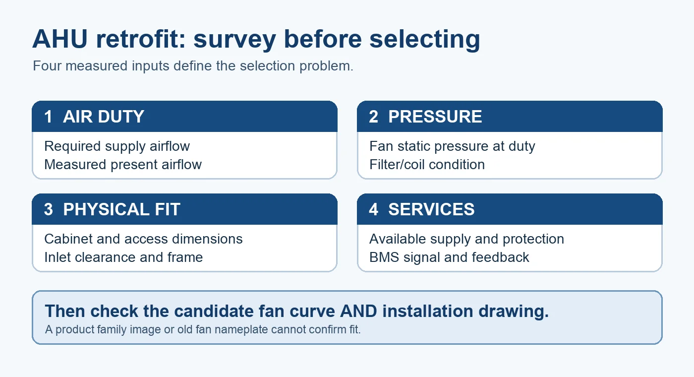
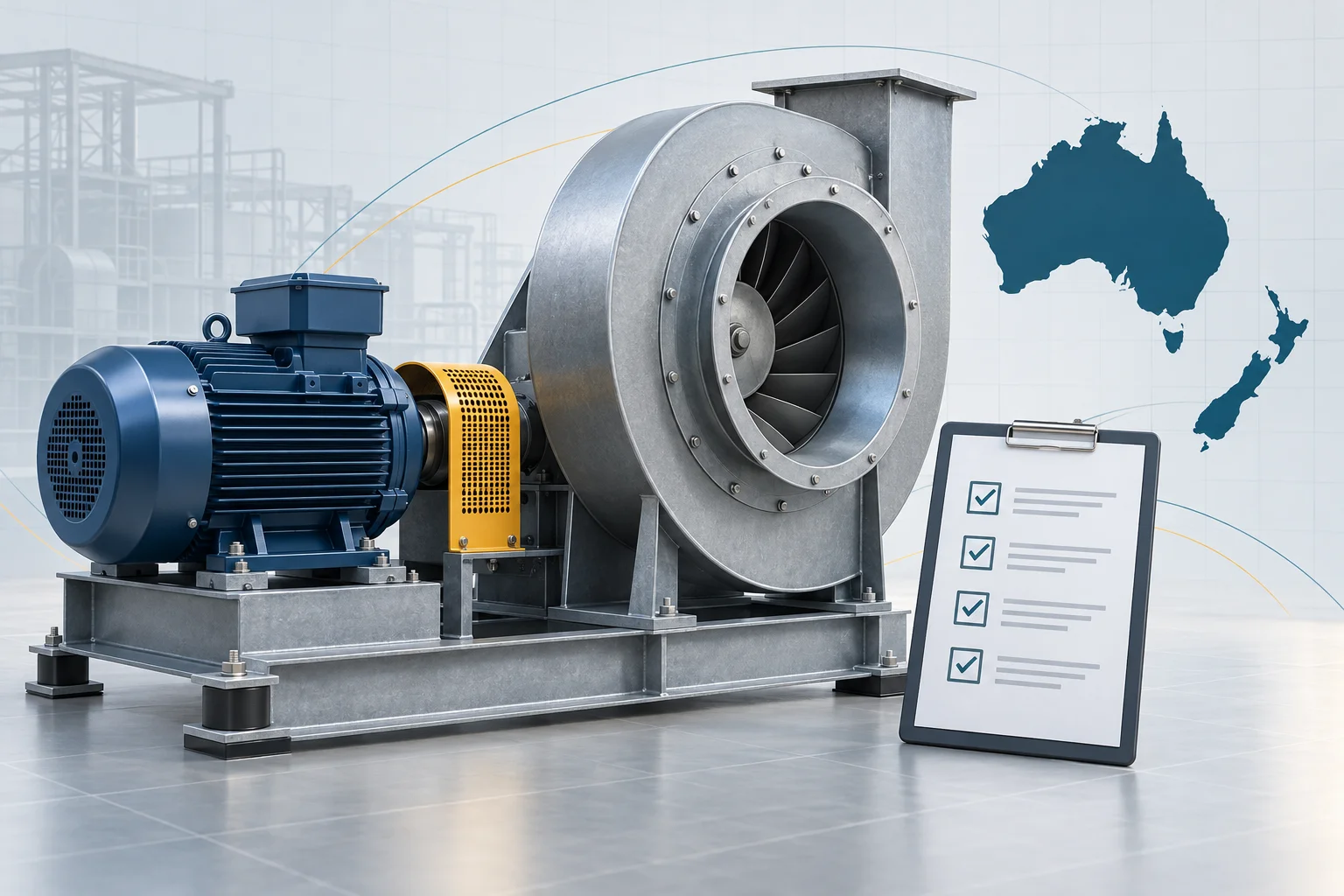
Figure 1 collects four inputs that should travel together: airflow, pressure, physical fit and services. If one is missing, the selection is provisional. A low resistance clean-filter point alone is not enough to check a later loaded-filter state, and a curve alone says nothing about whether the assembly can pass through the service door.
Choose a single fan or an array for the job
A single fan gives one assembly to mount and control. An array can help when the required flow is divided among several units, when service access favors smaller modules, or when the project has an explicit continued-operation requirement after one module stops. The array decision requires a calculation: the remaining fans, at their allowable speeds, must still meet the specified airflow against the common system pressure. The stopped module and its backflow path also need to be accounted for.
There is no universal airflow threshold at which an array becomes mandatory. Cabinet shape, pressure, redundancy policy, acoustic target and maintenance access all matter. LONGWELL’s FanGrid solution shows a family-level array arrangement; its marketing examples do not approve any particular retrofit duty or energy saving. Ask for the proposed fan count, exact variant, controls and the remaining-fan operating point before accepting an array proposal.
Read the exact model curve and its test boundary
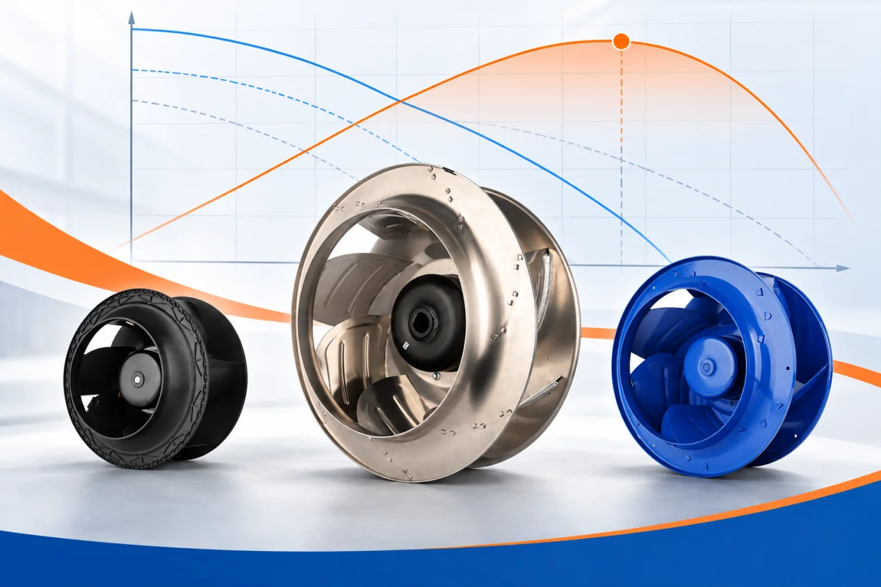
Place the required airflow and pressure on the current curve for the exact offered configuration. Check the selected speed or control setting, input power, allowed operating range and the test conditions used to make the curve. A curve for a wheel family is a route to a candidate, not proof for every mounting option, inlet treatment or motor suffix.
LONGWELL’s A0 engineering sheet for LWBE3G450-188NT-26-00, for example, includes a product drawing, wiring information and airflow/pressure tables tied to that full suffix. Those tables describe the documented configuration; they do not predict the completed AHU’s performance without accounting for inlet clearance, plenum geometry and system effects. Another LWBE3G450 suffix needs its own matching drawing and curve. The AHU plug-fan family is a place to identify candidate constructions, while final selection still requires the exact documents.
Confirm electrical supply and controls before ordering
List the supply voltage and phases available at the AHU, protective devices, earthing arrangement, cable route and space for glands. Ask for the exact candidate’s electrical and wiring specification rather than assuming every EC fan uses the same input. Several fans on one installation also require a review of total input, protection and control wiring.
Define the building management system’s command and feedback requirements. Is the command an analog voltage, a digital signal or a serial protocol? What should happen on signal loss, and what information must return to the controller? A family brochure may list available interfaces, but the selected suffix and ordered configuration determine the terminals and functions to wire. Put the agreed points and fault behavior on a controls schedule before installation.
Check the mechanical fit and airflow path
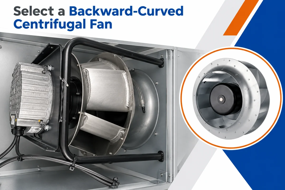
The product photograph below shows one LONGWELL EC plug-fan family construction: an open backward-curved wheel, motor and support frame. It helps explain why a retrofit may need a new frame and service arrangement. It does not show the actual AHU cabinet or prove that this pictured product fits it.
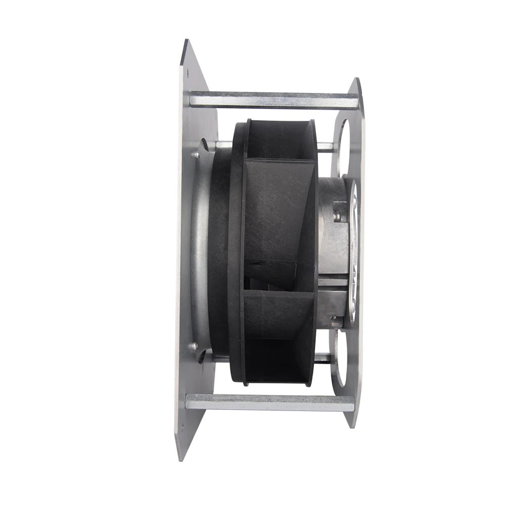
Overlay the exact candidate drawing on an AHU section. Check the inlet cone and approach space, frame fixing points, motor and wiring envelope, service removal path, and the route from wheel discharge to the next coil or filter. A plenum can permit a different layout from an old housed fan, but a specific cabinet-length saving cannot be inferred from the product photo. If a downstream component is close to the discharge, review air distribution and the relevant system effects with the AHU designer.
Commission on airflow, pressure and power
After installation, verify the actual airflow at the specified operating states using an appropriate measurement method. Record the pressure reference points and filter condition alongside each airflow result. Check that the controller can reach the specified state without driving the selected fan outside its allowed range. Record electrical input under the same conditions if energy use is to be compared.
Fan speed by itself is not an airflow measurement. Nor does replacing an AC assembly with EC automatically establish a percentage saving: the old baseline, control schedule, system resistance and operating hours determine the outcome. A defensible before-and-after comparison uses matched conditions or a documented adjustment method, with the measured input power and hours for each operating state.
Send a shortlist that can be checked
For each candidate, keep the model, full suffix, document revision, curve, drawing and control specification in one selection record. The shortlist should state the duty point and pressure boundary, the physical dimensions and access route, and what happens at the required part-load and fault states. Then compare quoted options on those common inputs.
Need an AHU retrofit selection review? Send the required airflow, pressure definition and cabinet section drawing to sales@longwellfans.com.