An EC fan in a semiconductor or pharmaceutical cleanroom does more than move air. It supports a particle-sensitive process boundary. A fan filter unit can slow down, a filter can load unevenly, or maintenance can disturb a ceiling zone while the room still appears normal. The engineering question is therefore how the complete FFU system protects the vulnerable process in every defined operating state.
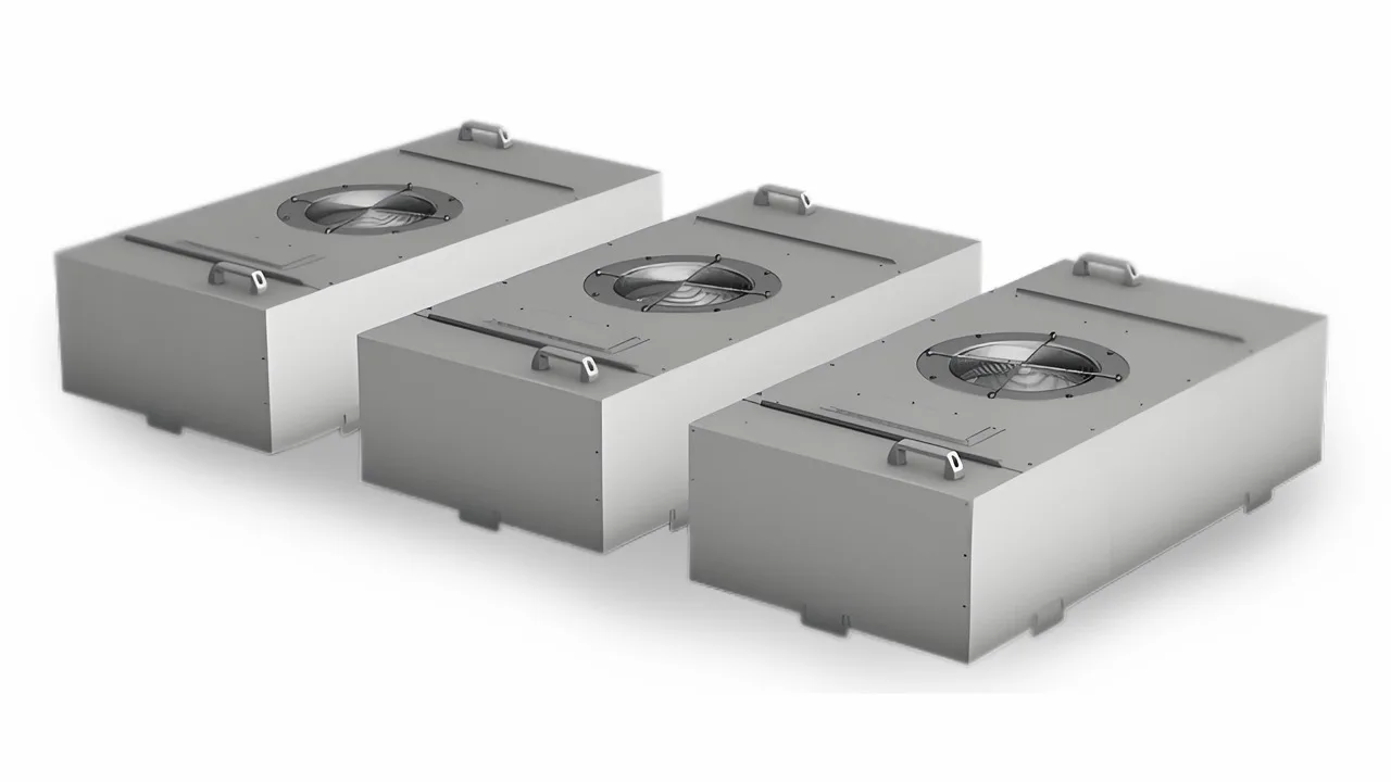
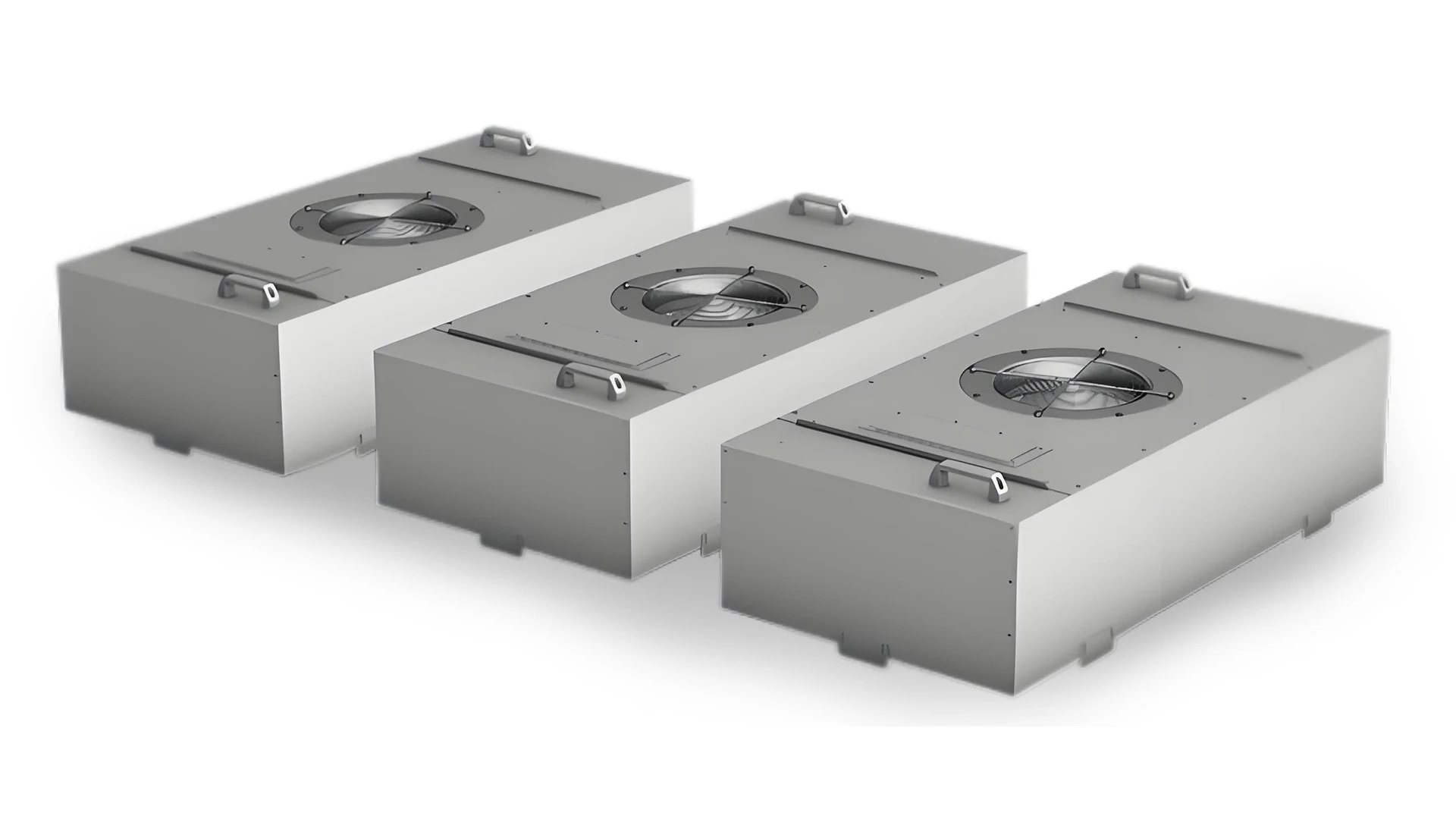
This guide explains how fans, filters, airflow paths, sensors, controls, redundancy, and maintenance fit into one cleanroom strategy. Longwell FFU imagery establishes physical architecture only; it does not prove a cleanliness class, airflow, filter grade, energy saving, redundancy outcome, or fab performance. Final design and acceptance must follow the project risk assessment, exact equipment data, applicable cleanroom standards, and measured installed results.
Define the Process Boundary and Complete Airflow Path
Conditioned air enters the ceiling plenum, an FFU fan draws it through the module, the final filter removes particles, and the supply face delivers clean air into the room or local zone. Air then passes tools, products, and people before entering the return path and moving back to the air-handling system. The critical boundary is the wafer, open product, filling area, or other vulnerable surface—not simply the center of an empty room.
A ballroom cleanroom, localized clean zone, and mini-environment create different contamination-risk maps. The fan strategy must follow the owner’s classification requirement, process layout, heat release, return-air arrangement, pressure relationships, and specified room state. There is no universal face velocity, air-change rate, or FFU ceiling coverage that can be copied safely from another facility.
Track Filter Loading and Spatial Uniformity
An FFU is a series system comprising inlet conditions, fan, housing, filter, diffuser, room, and return path. As particles accumulate, filter resistance changes and the operating point moves. Use a fan curve guide to keep airflow, pressure, speed, power, air density, and curve revision aligned, but approve the installed module against the complete system. A controller that holds only fixed speed may allow airflow to fall. If the project requires regulated airflow or pressure, fan capability, sensor location, control loop, filter states, and alarm limits must be engineered and commissioned together.
An average room reading can hide a weak ceiling module, filter bypass, a blocked return, or turbulence created by process equipment. Map airflow or velocity using the acceptance method appropriate to the specified room and airflow type, then examine the path to the protected zone. Repeatable protection at the vulnerable process is more important than a visually impressive average.
Connect EC Control to Verifiable Physical Response
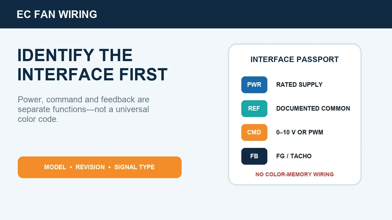
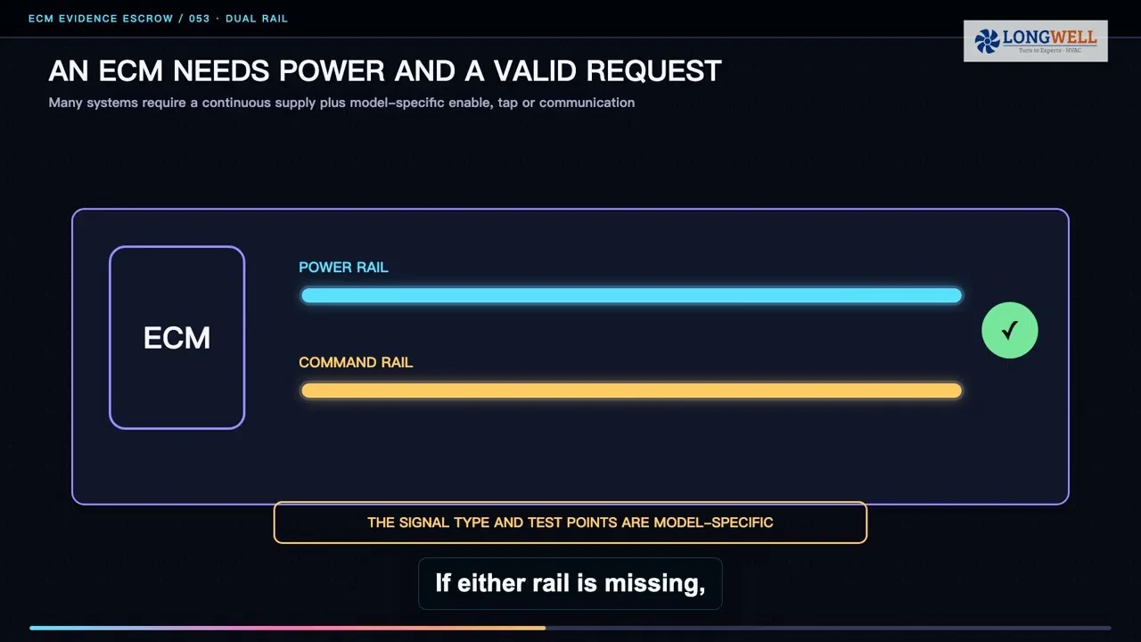
EC technology allows speed to be commanded and operating status to be observed, but it does not guarantee constant room conditions by itself. The Longwell EC plug-fan family is a discovery route, not a model selection or cleanroom-performance claim. A project control schedule should define enable, speed or airflow command, feedback, alarms, communications, and fail-safe behavior. It must also state what happens after a power interruption, lost sensor, communication failure, or FFU fault.
Each dashboard point needs a tested physical meaning. A speed indication should correspond to actual module response; an alarm should lead to the specified control and maintenance action. Signal definitions and available telemetry depend on the selected fan, FFU, and controller. Do not infer network capability, particle performance, or airflow regulation from an EC label or product photograph.
Test Spatial Redundancy and Maintenance Containment
Redundancy is spatial, not merely numerical. If one ceiling module stops, neighboring modules may increase output, but the resulting airflow field can shift around a critical tool or process. Test the defined module-out condition at the protected zone. Evaluate reverse leakage through an idle unit, common power feeds, shared controllers, local pressure effects, and whether one maintenance action can disable an entire bay.
An N+1 quantity on a schedule does not prove process protection. The designation is justified only when the installed failure scenario meets the project’s cleanliness, airflow, pressure, control, and equipment-limit criteria.
Maintenance is also part of contamination control. Define whether the fan, electronics, and filter are accessed from the ceiling or cleanroom side. Plan isolation, lockout, filter handling, tools, temporary barriers, cleaning, personnel movement, and recovery testing. Service speed is valuable only when the method preserves the clean boundary.
Commission Every Room State and Account for Energy
Every watt delivered to an FFU eventually becomes heat that the facility must remove. Evaluate measured electrical input across actual operating modes, including clean and loaded filters, reduced production, recovery, and fault states. Energy optimization must preserve the required contamination-control performance; a lower command is not a success if it weakens the process boundary.
The commissioning package may include filter integrity, airflow volume and uniformity, room pressure, airborne particle concentration, recovery, sound, vibration, electrical input, controls, and alarms, according to the project. ISO 14644-3:2019 provides cleanroom and clean-zone test methods, while IEST-RP-CC036.1 addresses comparable FFU test outputs. Record whether each test is as-built, at-rest, or operational because results from those states are not interchangeable.
Close the project with the required cleanliness condition and room state, layout, ceiling grid, return path, clean and loaded filter resistance, airflow and pressure targets, control interface, maintenance side, fault philosophy, sensor locations, test methods, and acceptance results. This evidence—not the presence of an EC fan—shows that the FFU system protects the process.
Choose the right ec fan
Longwell manufactures 34 ec fans in-house. Send airflow, static pressure and voltage — an engineer replies with a matching model, performance curve and price within one working day.