Short answer: choose a fan wall when the AHU must retain a defined duty after one module is unavailable or access makes a large fan difficult to remove. Choose one large fan when planned shutdowns are acceptable and simpler electrical, control, and maintenance arrangements matter more. Neither wins until both are checked at the same airflow, pressure, air condition, and installed boundary.
This is a system decision, not a fan-count contest. Compare normal, part-load, dirty-filter, and required failure cases while keeping visible geometry separate from measured performance.
Build one comparison sheet before requesting selections
Give both suppliers one design brief. State required airflow, whether pressure is static or total, air density or the temperature and altitude used to calculate it, filter and coil losses, damper positions, discharge condition, and the location of the measurement boundary. Add minimum, normal, and peak operating points rather than a single maximum.
Ask for complete-system curves on the same basis. Include the array’s proposed modules, partitions or spacing, plenums, controls, and backflow device; include the single fan’s drive, inlet, outlet, and plenum. Our guide to reading fan performance curves is a useful primer, but purchasing still needs current data for the exact quoted configuration.
Be precise about what “fan wall” means in this AHU
A fan wall or fan array uses two or more fans operating in parallel with a common inlet plenum, common outlet plenum, or both. That description does not promise redundancy, efficiency, low sound, or uniform coil-face velocity. Those outcomes depend on the selected modules and on how the array is installed and controlled.
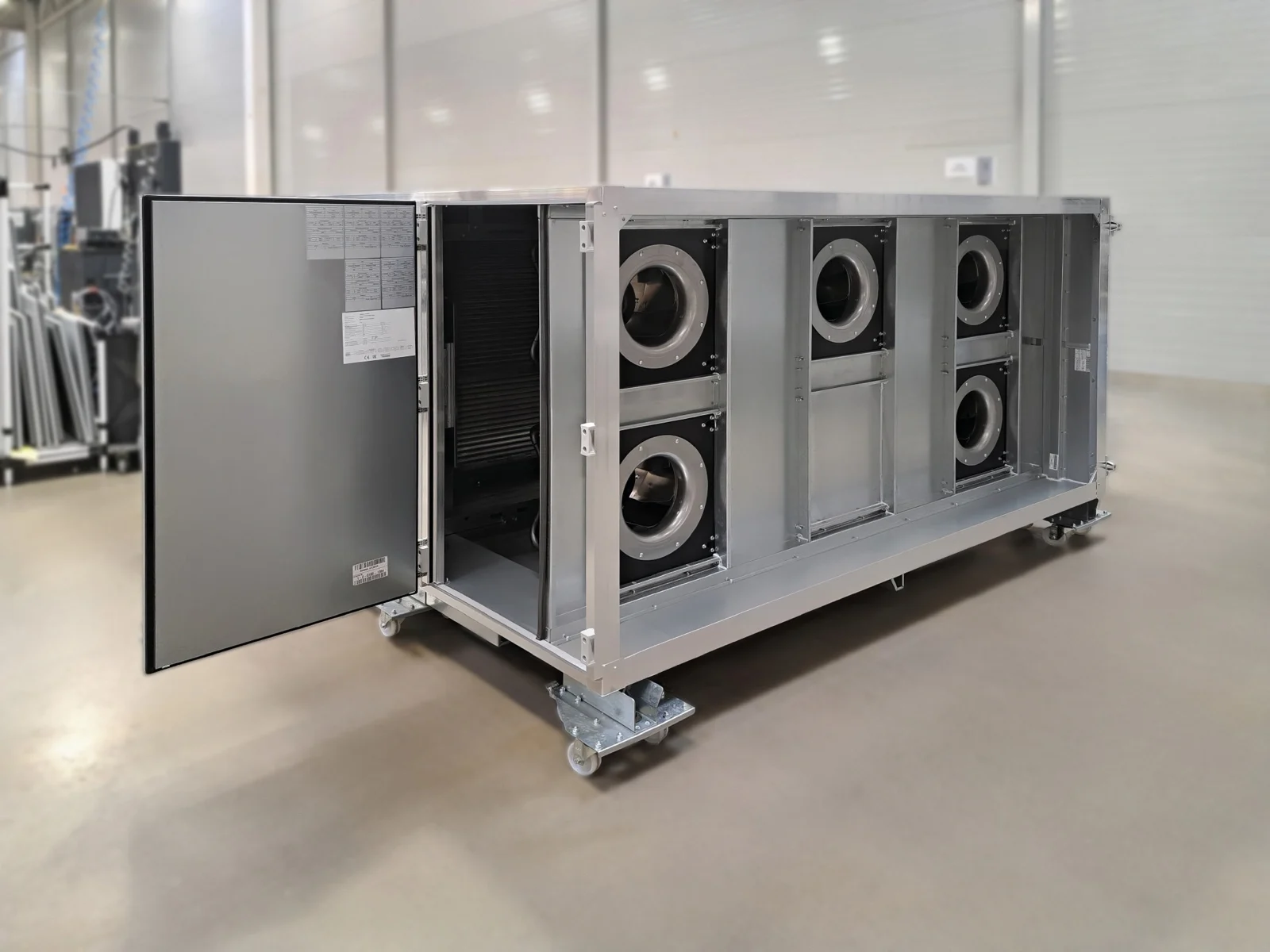
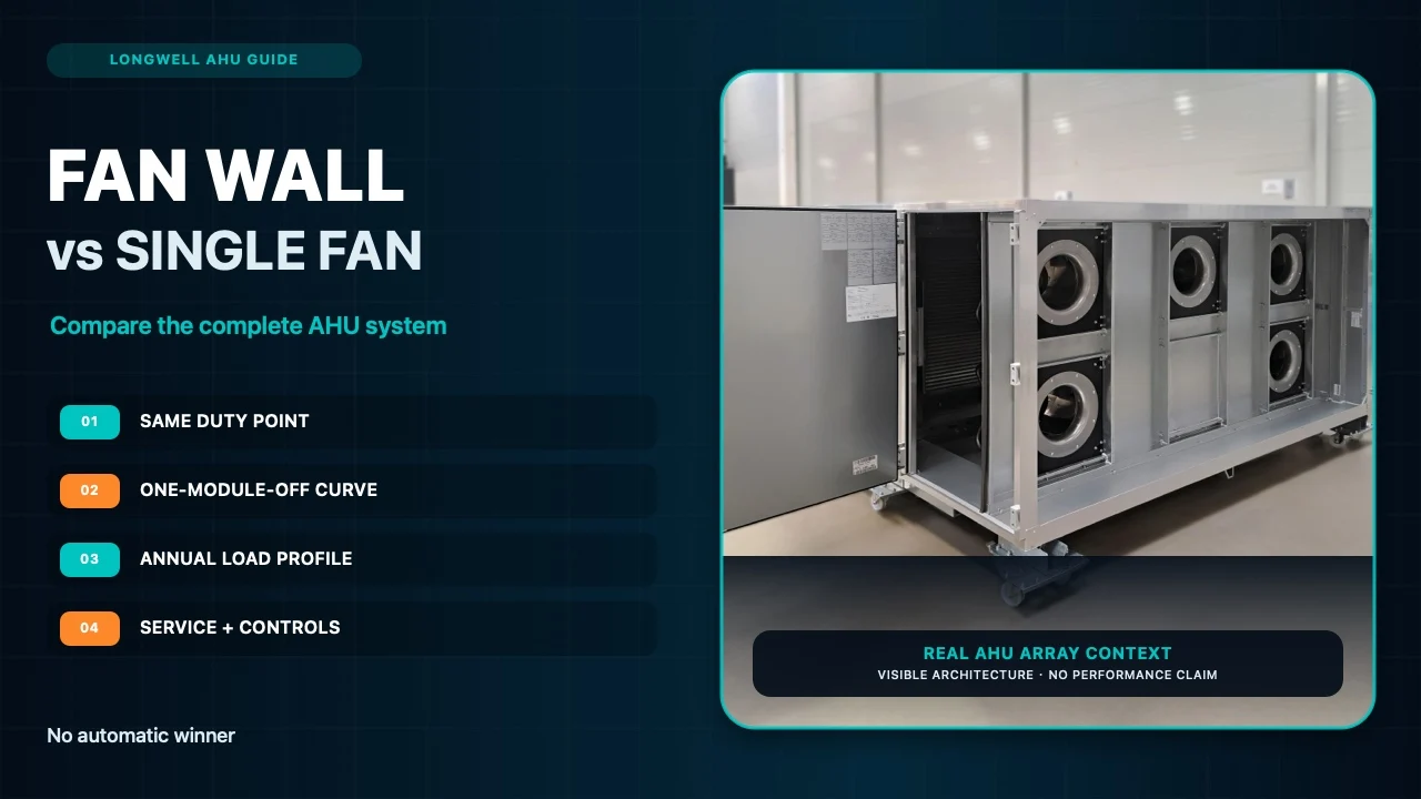
This real AHU application asset documents visible multi-fan architecture and access only. It is not a named customer result and proves no airflow, pressure, sound, energy, certification, or N+1 capacity.
If the basic architecture is still unsettled, the centrifugal fan-wall application overview provides a related navigation route. It cannot replace an array-level test or project selection.
Prove redundancy with the one-module-off operating point
Counting one extra fan is not an N+1 calculation. Identify the unavailable module, specify how reverse flow through that opening is limited, and plot the remaining array against the AHU system curve. The resulting operating point must meet the facility’s required failure duty without exceeding speed, current, electrical input, motor temperature, controller limits, or the manufacturer’s recommended operating range.
State whether the building requires full design airflow, a lower emergency duty, or simply continued air movement until shutdown. Then define fault detection, isolation, restart, alarms, and power-interruption behaviour. Remaining fans that spin do not prove the required duty.
Compare annual energy from the real load profile
A variable-speed single fan may perform well across its intended range. An EC array may run all modules together, stage modules, or vary the active modules as load changes. None of these control choices carries a universal savings percentage.
Divide the year into useful bins: occupied peak, ordinary occupied, low load, dirty-filter, and failure operation. Multiply verified electrical input at each required duty by expected hours, including controller and drive losses on one boundary. This ties annual energy to the building.
Staging also changes sound, restart behaviour, and module hours. Rotate lead duty only when the maintenance strategy calls for it; do not assume equal hours without a defined sequence.
Inspect airflow distribution, sound, and system effect
A distributed discharge can spread air across a coil face, but spacing alone is not proof. Inlet clearance, coil distance, bypass leakage, obstructions, a stopped cell, and downstream components alter the pattern. Review a velocity traverse or agreed commissioning method at normal and failure duty.
Sound varies with speed, staging, tonal content, plenums, ductwork, and measurement position. Compare sound power or sound pressure on a declared basis at the relevant operating points, never one free-field value with another installed reading.
Price the service task, not just the fan
A single fan has fewer motors, power feeds, controllers, communication nodes, and protective devices. Its drawback may be the size and weight of the assembly when service is required.
Smaller modules may improve handling only with safe isolation, guards, connectors, support points, and a clear extraction path. Draw that path, note what must be removed, set the spare policy, and decide whether service is allowed while other modules operate. Do not promise a fixed replacement time before reviewing access.
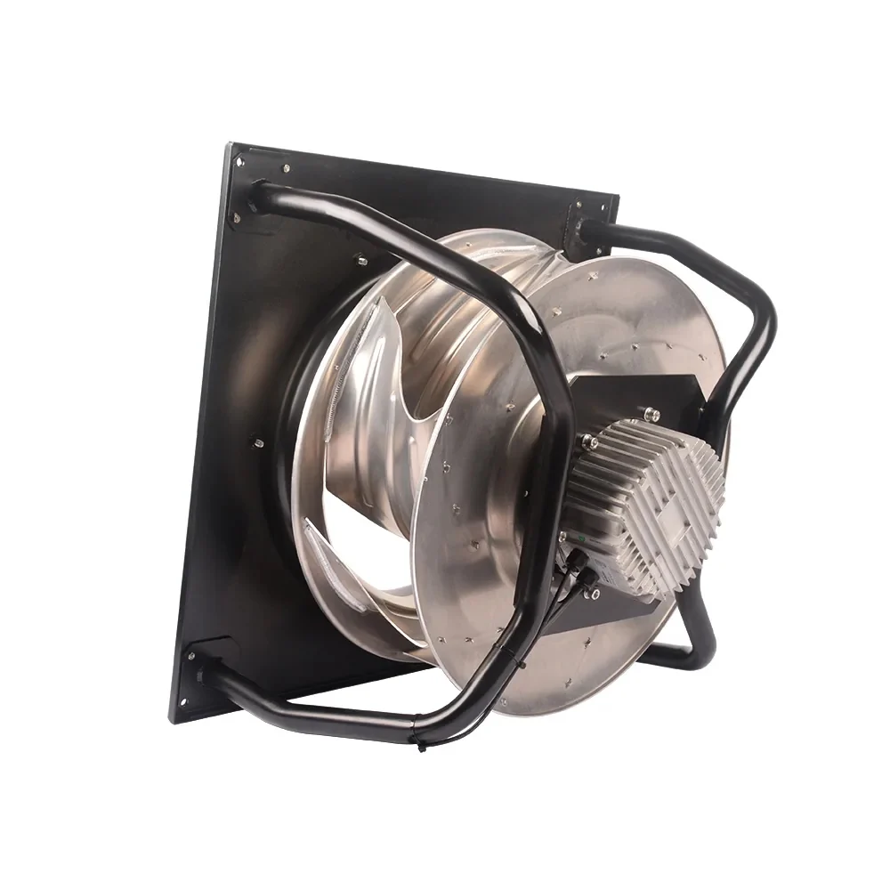
This LONGWELL library photograph is labelled LWBE3G630-188PT-04 and shows visible plug-fan, motor, mounting plate, and support geometry. The filename does not establish the current project revision, duty point, array spacing, controls, compatibility, or certification. The LONGWELL centrifugal fan family can be used to browse available architectures; final selection still requires an exact suffix and controlled documents.
Make the controls and electrical comparison explicit
For each option, list supply voltage and frequency, branch protection, disconnects, cable routes, speed command, communications, fault outputs, sensor dependencies, restart logic, and commissioning access. A fan wall may expose more individual status information, yet it also creates more devices to address and maintain. A single-fan system may be simpler but still needs a defined failure and restart strategy.
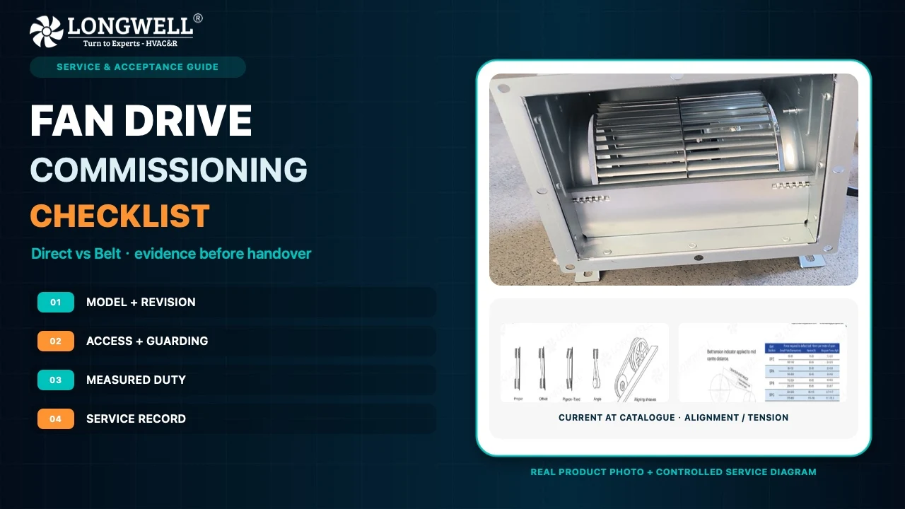
Check every identifier on the quotation. A family name or diameter is not a complete model. Use a line-by-line specification review to catch missing suffixes, mixed pressure definitions, and control assumptions before they become purchase-order problems.
Use an RFQ that produces a defensible answer
- Normal, minimum, peak, dirty-filter, and required failure duty points.
- Static or total pressure basis, air density, and complete AHU resistance calculation.
- Arrangement drawing with plenums, clearances, coil distance, bypass sealing, and removal path.
- Exact model, full suffix, drawing and performance-data revisions for every proposed fan.
- Normal and one-module-off array curves, including electrical input and operating limits.
- Control narrative for staging, fault isolation, alarms, restart, and lead rotation if used.
- Sound data and test boundary at the required normal and failure operating points.
- Commissioning plan for airflow, pressure, electrical input, controls, and coil-face distribution.
- Installed cost, critical spares, planned service procedure, and accepted downtime.
That evidence may favour either architecture. The fan wall offers modularity only when the one-module-off duty and service design are verified. One large fan offers simplicity only when its shutdown and removal consequences are acceptable. Put both on the same system curve, run the same operating scenarios, and let the project requirements decide.