A thermal trip is a stop signal, not a diagnosis. It says that a protection function has operated. The next decision is to identify which device acted, preserve the operating evidence, and find the cause before the fan is released. Resetting without that work can erase the clue and repeat the fault.
First identify the exact motor and protection device
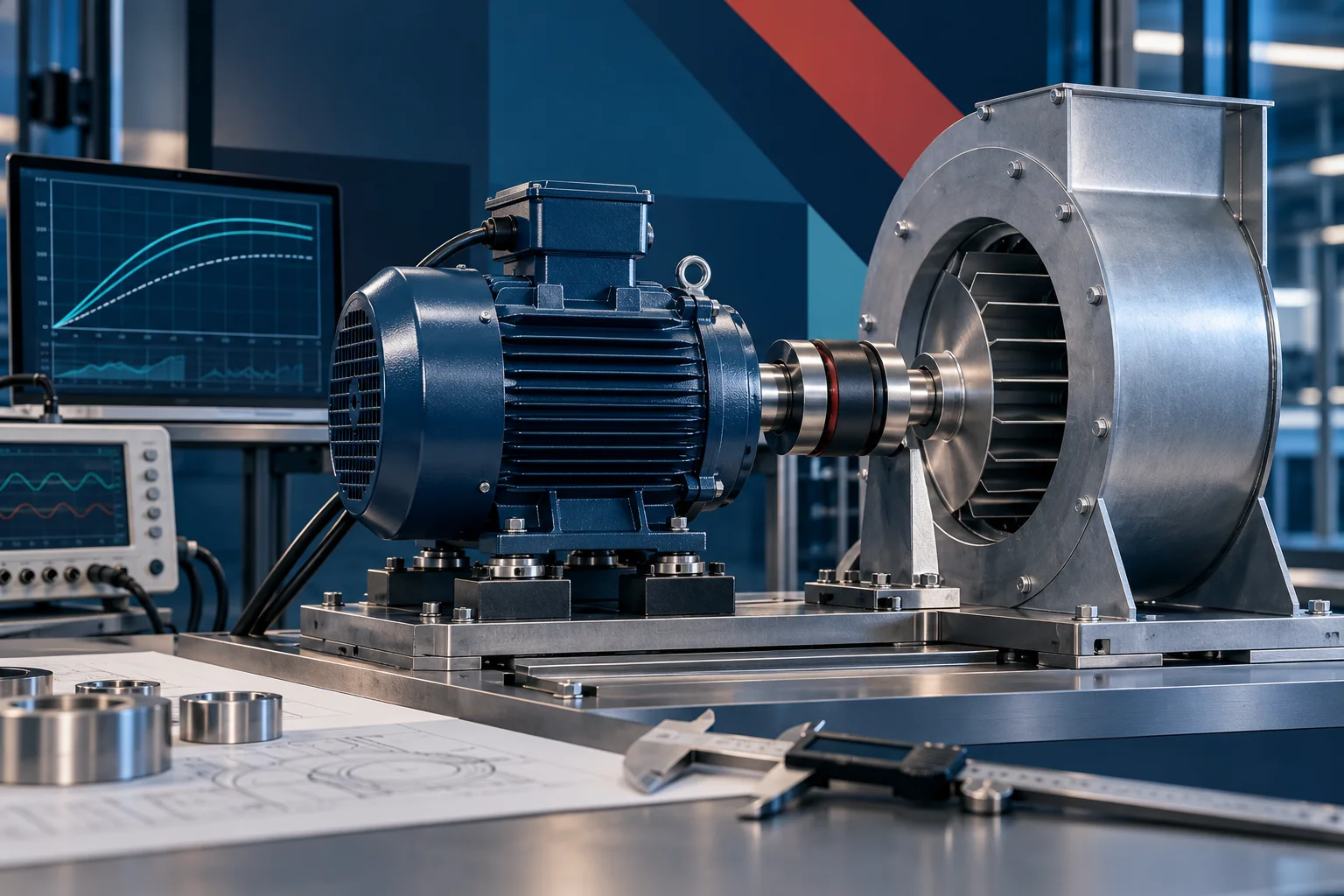
Record the complete fan and motor designation, suffix, nameplate, supply, control method and the revision of the applicable wiring sheet. An AC motor with an internal thermal protector, a panel overload relay, and an EC fan with electronic fault handling are different systems. The video explains the principles; it does not set a trip value for every LONGWELL fan.
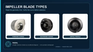
One bounded company example is the LONGWELL LWFA2E120-092SU-08 AC forward centrifugal fan: its A1 specification lists a thermal protection function and separately calls for over-current protection. Those are two distinct requirements for that exact revision. They do not establish the protection arrangement, reset behavior or settings of another LWFA2E120 suffix. The forward-curved centrifugal fan family is a product path, not a substitute for the selected unit’s drawing and instructions.
Current-based protection and winding-temperature sensing answer different questions
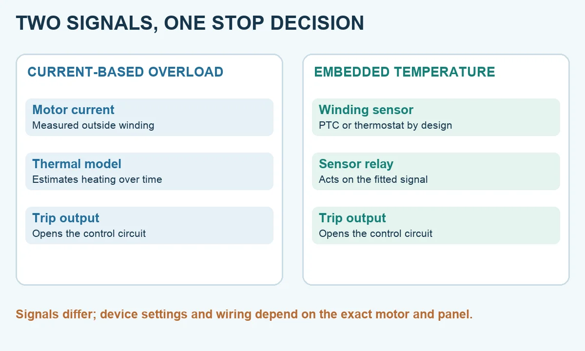
A current-based overload relay or electronic motor controller observes motor current and estimates heating over time. It can account for how long a high-current condition lasts; the trip curve and cold or warm starting state matter. A winding PTC thermistor, thermostat or other fitted sensor responds to temperature at its installed location. It must be connected to the specified relay or control input and to a stop function that actually interrupts operation.
The two paths can complement one another, but neither is a universal fault detector. A current-based relay does not directly measure winding temperature. A temperature sensor does not replace the separate short-circuit and supply-fault protections required by the complete installation. ABB’s UMC100.3 manual explicitly distinguishes load-current thermal overload from PTC resistance sensed in motor windings. The schematic below shows that signal difference, not a wiring diagram for a particular LONGWELL model.
Why trip class and reset behavior cannot be guessed
An inverse-time overload can tolerate a brief starting current but trip sooner when a more severe overcurrent persists. A trip class describes a defined relay characteristic; it is not a recommended setting for every fan. The ABB controller manual above shows distinct trip curves and ties selection to the protected motor. Use the actual motor data, relay manual and coordination requirements when selecting a device.
Reset behavior also belongs to the fitted hardware and control design. Some protectors can reset after cooling; other arrangements require a deliberate reset. A stop followed by a later restart could be thermal action, a controller command or another fault path. The interval alone cannot identify the cause. Treat any unexpected restart as a hazard during diagnosis and follow the site’s isolation procedure.
Follow the complete trip chain
Ask what sensed the condition, what logged the fault, which contactor or drive output stopped the motor, and whether any alarm reached the operator. A sensor without a working stop path is not effective protection. Record the fault code or relay indication before clearing it. For an EC fan, read the exact controller instructions rather than assuming it slows, latches, auto-resets or reports over a bus; those features vary by model and configuration.
Do not use a hand-held surface reading as a winding-temperature reading. The case, the sensor location and the winding can be at different temperatures. Compare any measurement with the specified location, operating point and limit for the exact motor. The related fan-motor overheating guide explains how to capture supply, load and cooling evidence without turning one symptom into a diagnosis.
Investigate causes in separate branches
On the electrical branch, a qualified person checks supply voltage, phase condition where applicable, measured current, protection settings and fault history against the nameplate. On the mechanical branch, inspect for rub, damaged bearings, imbalance, loose mounting or contamination after safe isolation. On the air and cooling branch, establish how this motor is cooled, then check its actual vents, ambient and operating speed. Process airflow and motor cooling are not always the same path.
Fan loading must be evaluated at the installed duty. A filter, damper or duct change can shift the operating point, but the direction of motor-current change depends on the fan curve and control method. Do not claim that every restriction increases current or that every trip is a blocked-airflow event. A capacitor check is relevant only if the exact motor uses that component. Short circuit, phase loss, ground fault, overload and overtemperature are different functions; identify which one acted before choosing a repair.
Use a documented release decision
After isolating the equipment, retain the full model and revision, fault indication, supply and current readings at a defined duty, command or speed, ambient condition, and photographs of the installation. Compare them with a known good baseline when one exists. A qualified technician can then address the demonstrated cause, confirm the specified protection devices and settings, and test the corrected assembly under its required operating condition.
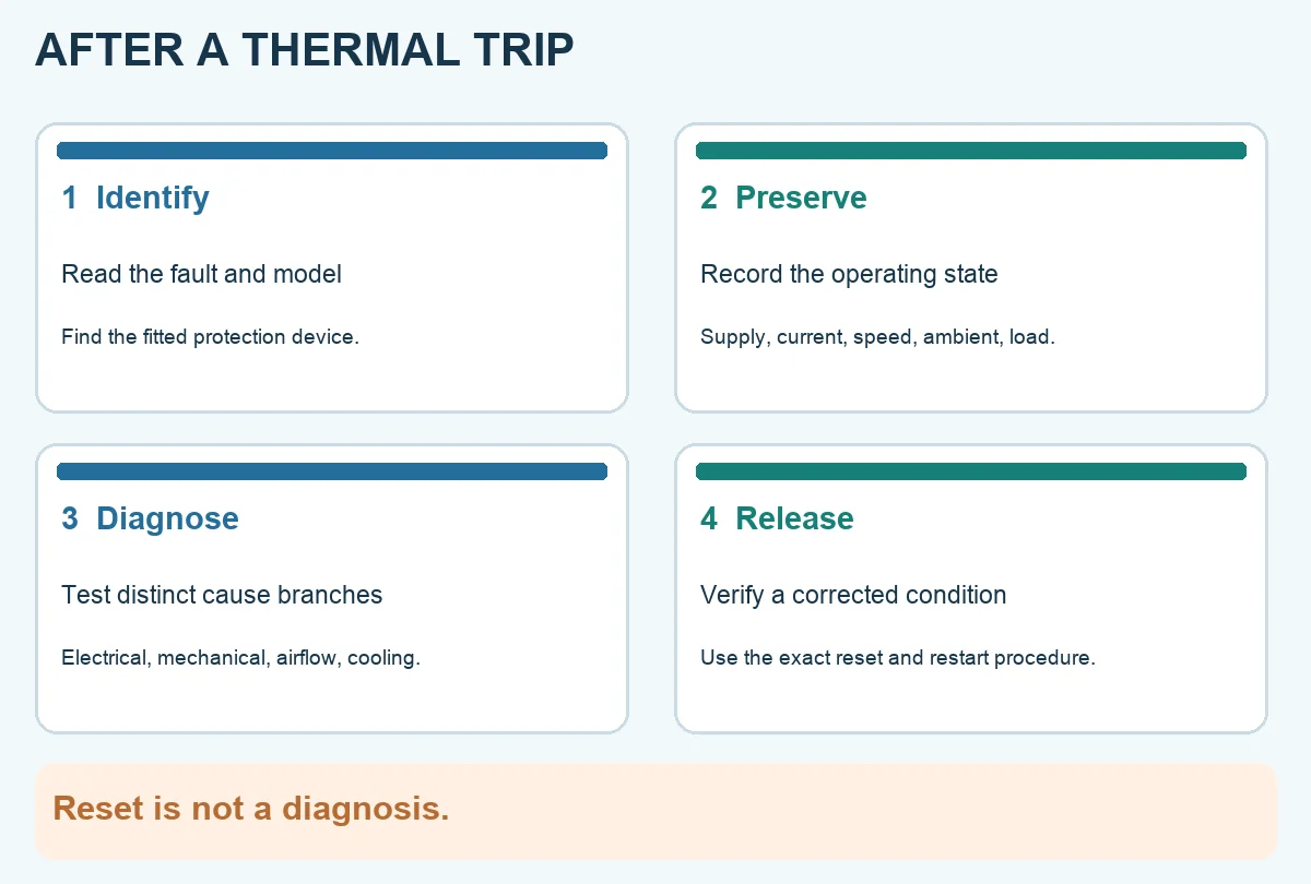
The diagram is deliberately free of a universal trip temperature, current or reset timer. The A1 example identifies one model’s documented protection, while the panel design and final settings still require the exact project documents. Never bypass a protector or increase a relay setting merely to stop repeated trips.
Watch the protection walkthrough
The video follows current-based thermal memory, embedded sensors, the trip chain and the evidence needed before reset. Use it to frame the questions to ask; use the selected motor and protection-device instructions for the actual settings.
Need an engineering review? Send the complete fan model, protection-device details and operating evidence to sales@longwellfans.com.
Choose the right forward curved centrifugal fan
Longwell manufactures 93 forward curved centrifugal fans in-house. Send airflow, static pressure and voltage — an engineer replies with a matching model, performance curve and price within one working day.