A fan order written like an electrical contract
A commercial HVAC OEM ordered a 350mm EC axial fan for condenser arrays: 3432 m3/h on a 230 VAC single-phase rail, inside 62 dB(A). What set the order apart was the EC fan wiring specification, which named every conductor on both connectors.
On the power side: brown live, blue neutral, yellow-green earth. Meanwhile the control side carries five more wires, each with a job.
The physical envelope
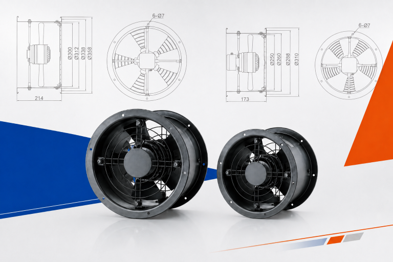
- First, a 422mm outer ring and exactly 122mm of depth, set by the chassis.
- Next, -25C to +60C ambient with IP54, since the units live outdoors.
- Meanwhile S1 continuous duty, Class F insulation and 0 to 85% humidity.
- Finally, CE with EN 60335-1, GB 12350 and ISO 5801 validation.
Why the wiring paragraph matters
An EC fan is not just an air mover; it is a node on the machine control system. Consequently, the interface between fan and controller is where integration succeeds or dies.
A customer who writes the EC fan wiring out completely has been through the alternative: a fan that arrives, fits, spins, and cannot talk to the board it must obey.
Reading the EC fan wiring line by line
The control connector carries five conductors, and reading them in order shows what complete EC fan wiring looks like.
The command wires
First, a yellow wire accepts the speed command as either 0-10 VDC analog or PWM, and the PWM is bounded properly: 1 to 10 kHz frequency, 10 to 12 V amplitude. Those bounds matter, because PWM outside the accepted band produces a fan that hunts or ignores the signal.
A red wire supplies +10 VDC out of the fan itself, so a simple potentiometer can command speed with no external supply. Meanwhile a separate brown wire takes a 4.5 to 20 mA current-loop input, the alternative command form industrial controls often prefer over voltage.
The feedback wires
Next, a green FG wire reports the actual speed, one pulse per revolution, as an open-collector output needing an external 10 kilohm pull-up. That resistor detail can stop a commissioning day dead when it is missing. The signal exists, the wire is right, and the input reads nothing.
Lastly, blue is the signal ground, kept separate from the power neutral. That separation protects the control signals from the noise the power side carries.
Why bounds beat labels
Naming a wire PWM is a label. By contrast, stating 1 to 10 kHz at 10 to 12 V is a boundary a controller designer can verify against their output stage before anything ships.
Here the same goes for the current loop. Stating 4.5 to 20 mA says where the fan starts listening, so the dead zone at the bottom of the range is documented rather than discovered.
What we validated
In the end, we verified every conductor against the customer color plan, and we tested the tach behavior with the specified pull-up rather than a lab convenience. Aerodynamic figures follow ISO 5801 methods.
Technical Specifications
The airflow rows below took one line each to agree. The control interface took a paragraph, and it deserved one.
| Parameter | Specification |
|---|---|
| Model Number | LWAE3G350SS-5PEW-09 |
| Nominal Voltage | 230 VAC |
| Voltage Range | 198~277 VAC |
| Frequency | 50/60 Hz |
| Speed | 1700 RPM |
| Current | 1.4 A |
| Power Input | 188 W |
| Air Flow (Max) | 3432 m³/h / 2019 CFM |
| Noise Level | 62 dB(A) |
| Max. Ambient Temp | 60 °C |
| Min. Ambient Temp | -25 °C |
| Insulation Class | Class F |
| Protection Type | IP54 |
| Work System | S1 |
| Dielectric Resistance | AC1800V |
| Leakage Current | 3.5MAX (mA) |
| Life Expectance | 30,000 Hours (L10) at 40°C |
| Balancing Standard | JB/T 9101-1999 G6.3 |
| Impeller Material | PA6+30%GF |
| Bearing Type | Maintenance-free deep groove ball bearings |
| Speed Control | Control input 0~10VDC / PWM |
| Certifications | CE, RoHS, Reach |
Technical Documentation

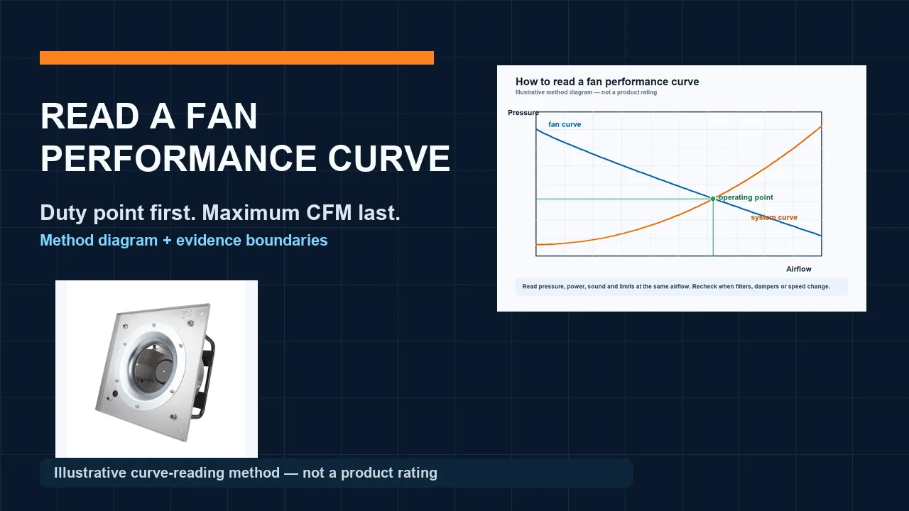
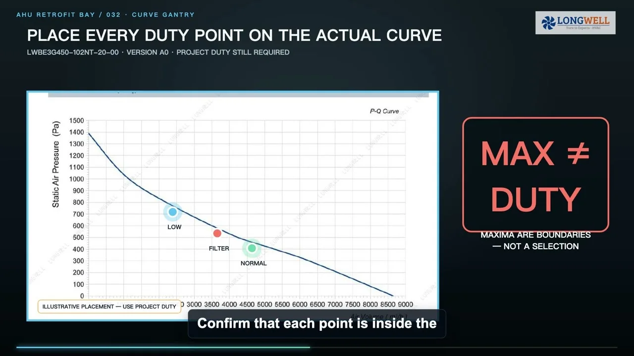
This initial performance curve and product characteristic sheet allows HVAC design engineers to map the exact static pressure and airflow intersection against their specific system impedance, ensuring the 1700 RPM speed matches thermal loads.
LWAE3G350SS-5PEW-09 Editable Source Document
This editable DOCX source file provides OEM procurement managers and internal documentation teams with the exact technical text, test parameters, and electrical tolerances needed to integrate fan specifications directly into their proprietary ERP systems.
LWAE3G350SS-5PEW-09 Technical Specification PDF
This comprehensive 8-page engineering file includes detailed wiring diagrams, precise dimensional drawings extending to a 422mm outer diameter, and CE compliance data required by system integrators during the strict final QA approval stage.
Writing your own interface spec
If your product integrates an EC fan, write the EC fan wiring the way this customer did. Four rules cover most of it.
- Specify signal bounds, not signal names. Complete EC fan wiring states the PWM frequency band, the amplitude window and the analog range. Otherwise, a controller built to unstated assumptions works on the bench and fails on the variant.
- Fix the wire colors in the order. Color conventions differ between suppliers and regions. Stating your color plan costs six lines and prevents the crossed pair that no continuity test catches, because both wires do connect to something.
- State the tach pull-up explicitly. An open-collector speed output needs a pull-up resistor, and someone must own it: fan side or board side. Write down which, and the value, or commissioning will find out the slow way.
- Keep signal ground and power neutral apart. They are different conductors doing different jobs. EC fan wiring that ties them together invites the motor switching noise straight into the speed signal it is supposed to obey.
See our axial fans range, the EC axial fans section, or condenser fans.
Questions about EC fan wiring
Should I control the fan with 0-10V or PWM?
Both reach the same speeds. Rather, the difference is in your controller. Analog 0-10V is simple and noise-sensitive over distance, while PWM tolerates longer runs but must sit inside the frequency and amplitude window the fan accepts. Pick whichever your board produces cleanly, and state it.
What is the 4.5 to 20 mA input for?
It is the current-loop alternative to voltage control, common in industrial automation because current signals resist noise over long cable runs. Additionally, the 4.5 mA floor gives fault detection: a broken loop reads zero, which is distinguishable from a valid minimum command.
Why did my tach signal read nothing at commissioning?
Meanwhile the classic cause is the missing pull-up resistor. After all, an open-collector output does not produce a voltage on its own; it pulls a supplied voltage down. Without the resistor the input floats, the meter reads nothing, and the fan gets blamed for a board-side omission.
Does one pulse per revolution limit what monitoring can do?
It sets the resolution, not the principle. For instance, one pulse per rev updates fifty times a second at 3000 RPM, ample for stall detection and trend monitoring. Higher pulse counts refine low-speed readings, which matters mostly below a few hundred RPM.
Technical Documentation & Resources
Need the same thing for your own unit?
Give us the numbers and the envelope, and you get a shortlist rather than a catalog. Meanwhile custom spec sheets and samples run to 90 days. Since 1990 Longwell has supplied EC fans and blowers to OEMs in HVAC, cold chain, data center and industrial markets.
Browse Related Products:
🏆 ISO 9001 / ISO 14001 / ISO 45001 | CE (TÜV) | UL/ETL | ATEX Zone 21/22 | AMCA 210/211 / ISO 5801 tested
Choose the right ec axial fan
Longwell manufactures 152 ec axial fans in-house. Send airflow, static pressure and voltage — an engineer replies with a matching model, performance curve and price within one working day.