Defining Needs for an Industrial Centrifugal Fan
The sales team received a request for an industrial centrifugal fan. A customer needed it for a cement plant dust filter. These material handling spaces are very dusty. Therefore, the blower must move heavy dust loads safely.
It cannot suffer fast mechanical wear. First, the main rule required an airflow of 15,000 m3/h. The static pressure target was 250 mmH2O. This pressure equals about 2451 Pa.
Consequently, this shows a highly blocked filter design. Next, the buyer asked for a direct-drive setup. The 220V/380V three-phase AC motor must handle constant voltage shifts. The power limit was tightly capped at 18.5 kW to match existing breakers.
Furthermore, they needed a strict LG0 output shape. This means the case needs left-hand spin. The air must exit straight up at a 0-degree angle to match roof ducts. Meanwhile, the brief stated a high air heat of 40 C to 50 C.
This hot limit warns engineers about motor heat risks. Moreover, we had to add a clean-out door on the case. Routine cleaning requires this door. Finally, the buyer expected tests matching ISO 5801-1997 and AMCA 210-16 methods.
Testing against AMCA 210-16 ensures the pressure curve is exact. ISO 5801-1997 confirms the acoustic and air flow traits. Meeting these strict standards proves the air flow claims are true. By contrast, untested units often fail to reach 2451 Pa in real ducts.
Choosing the Motor and Impeller Geometry
Designers facing high-pressure dust jobs pick between a few rotor shapes. First, we looked at a basic forward-curved wheel. However, we tossed this idea out fast. Cement dust builds up tightly between close blades.
This dust trap causes heavy rotor wobble. Then, it wrecks the bearings quickly. Next, we checked a belt-driven layout. Belt systems use pulleys to adjust speed easily.
Instead, we dropped that plan completely. The buyer firmly asked for a direct-drive industrial centrifugal fan. They wanted to save floor space in a crowded factory. Belt drives take up too much room. They also require constant belt tension checks.
Material Costs and Rotor Weight
So, we picked a tough backward-curved wheel for this industrial centrifugal fan. We built both the wheel and the outer shell from thick steel plates. Furthermore, we sprayed a special hard epoxy coating on the metal. This paint fights off damage from sharp cement grit hitting the fan at high speed.
Even so, this strong design has a clear price. Thick steel and heavy paint add a lot of mass. Therefore, spinning this heavy wheel to 2900 RPM needs high starting power. The buyer had to upgrade their electric panel.
They needed parts that handle longer power spikes during start-up. A heavier wheel simply takes more seconds to reach full speed.
Motor Heat Limits and Final Rules
Standard room fans often rest during the day. By contrast, this heavy task needed steady S1 continuous running under a huge load. The chosen industrial centrifugal fan, model LW4-72-5.6A-002, uses a YE3 high-efficiency 18.5 kW motor. The buyer wanted an IP55 seal to block out fine dust.
They also set a 50 C ambient heat limit. Meanwhile, our normal data sheet lists IP54 and a 40 C ceiling for this motor type. Consequently, we warned the buyer about the heat risk. Running near 50 C at 18.5 kW leaves almost no heat safety net.
The Class F wire wrap might age faster over time. Finally, they agreed to this limit. They will plan their upkeep checks using our data curves to prevent failures.
Technical Specifications
| Parameter | Value |
|---|---|
| Model Number | LW4-72-5.6A-002 |
| Air Flow | 10,109 – 20,216 m3/h |
| Static Pressure | 2195 – 3465 Pa |
| Speed | 2900 RPM |
| Motor Power | 18.5 kW (YE3 Motor) |
| Voltage | 3~380 VAC |
| Frequency | 50 Hz |
| Operating Temperature | -20 C to 40 C |
| Insulation Class | F |
| Protection Type | IP 54 |
| Work System | S1 (Continuous) |
| Bearings | Maintenance-free deep groove ball bearings |
The static pressure row matters most for this industrial centrifugal fan. Therefore, hitting up to 3465 Pa at peak allows the 18.5 kW motor to push past dirty filters. Furthermore, the S1 work system proves the unit can run non-stop all year without cooling breaks. The maintenance-free deep groove ball bearings handle the high 2900 RPM speed easily. These sealed bearings stop fine cement powder from destroying the rolling balls. Finally, the IP54 protection blocks harmful dust from touching the sensitive motor wires.
Reference: IEC 60529 covers the test method behind these figures.
Technical Documentation

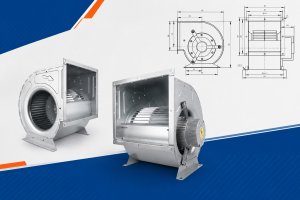
This drawing shows the LG0 mounting shape for proper duct alignment. Installers use this guide to orient the heavy steel casing correctly.

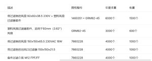
The input sheet here lists hard rules like the 18.5 kW limit and 250 mmH2O target. It proves exactly what parameters the sales team captured before engineering began.
Download LW4-72-5.6A-002 Technical Data Sheet
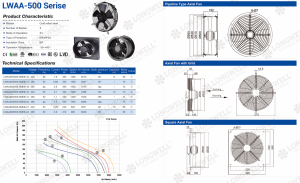
Our approved file holds exact sizes and test curves for system planners. Buyers refer to these PQ flow charts to map out their expected air volume drops.
How to Plan Your Own Heavy Particulate Blower
Engineers building dirty air systems must check key details early.
- First, lock in your exact output angle and spin direction. You cannot simply rotate the casing easily on site because fixing heavy welded steel boxes is very hard.
- Next, demand clean-out doors on the outer shell. Dust will always gather inside the lower case. Therefore, easy access stops bad shaking issues before they destroy bearings.
- Also, find your true worst-case filter drag. High static pressure limits force you to buy larger, costlier motors. Guessing this number often leads to weak air flow.
- Finally, state your real highest air heat. Running a heavy steel wheel near 50 C stresses the motor heavily. Consequently, you must watch the wire heat ratings closely to avoid fires.
In short, gathering these facts saves time and prevents fast breakdowns. We make our own thick steel wheels, which speeds up custom fits.
Related: Centrifugal Fans.
Engineering FAQs for Dust Filter Blowers
Technical Documentation & Resources
Browse our axial fans range, the AC axial fans section, or EC axial fans.
Have a Similar Fan Requirement?
Longwell’s engineering team delivers custom spec sheets and samples within 90 days. Since 1990, we have supplied EC fans and blowers to OEMs across HVAC, cold chain, data center, and industrial applications worldwide.
Browse Related Products:
🏆 ISO 9001 / ISO 14001 / ISO 45001 | CE (TÜV) | UL/ETL | ATEX Zone 21/22 | AMCA 210-16 / ISO 5801 tested
Choose the right centrifugal fan
Longwell manufactures 1,130 centrifugal fans in-house. Send airflow, static pressure and voltage — an engineer replies with a matching model, performance curve and price within one working day.