Data-center cooling redundancy passes only when the approved failure test keeps representative server inlets within the project limit. A room-average temperature, an N+1 label, or a surviving fan count cannot prove that result. The useful test follows the hottest inlet from normal operation through failure detection, airflow redistribution, peak temperature, and recovery.
This guide focuses on that system-level decision. It does not select a fan model or define an availability tier. Use the actual rack-load map, air-cooled heat share, inlet envelope, air density, pressure losses, control sequence, electrical paths, and approved failure classes for the project.
Freeze the protected boundary before calculating airflow
Start with heat by row, rack, and height. Separate heat removed by liquid cooling from the share that must enter the room air. Record the normal load, credible growth, planned-maintenance state, and the load present during each failure test. Two rooms with the same total kilowatts can behave differently when one has concentrated high-density racks or an end-of-row hotspot.
Next, define what must be protected. Use the approved server-inlet temperature and humidity envelope, not only a return-air or wall-sensor target. Select representative inlet sensors at the top, middle, and bottom of critical racks. State the test duration, allowable transient, sampling interval, and pass/fail rule before the equipment response is known.
Translate the air-cooled heat into a checkable airflow basis
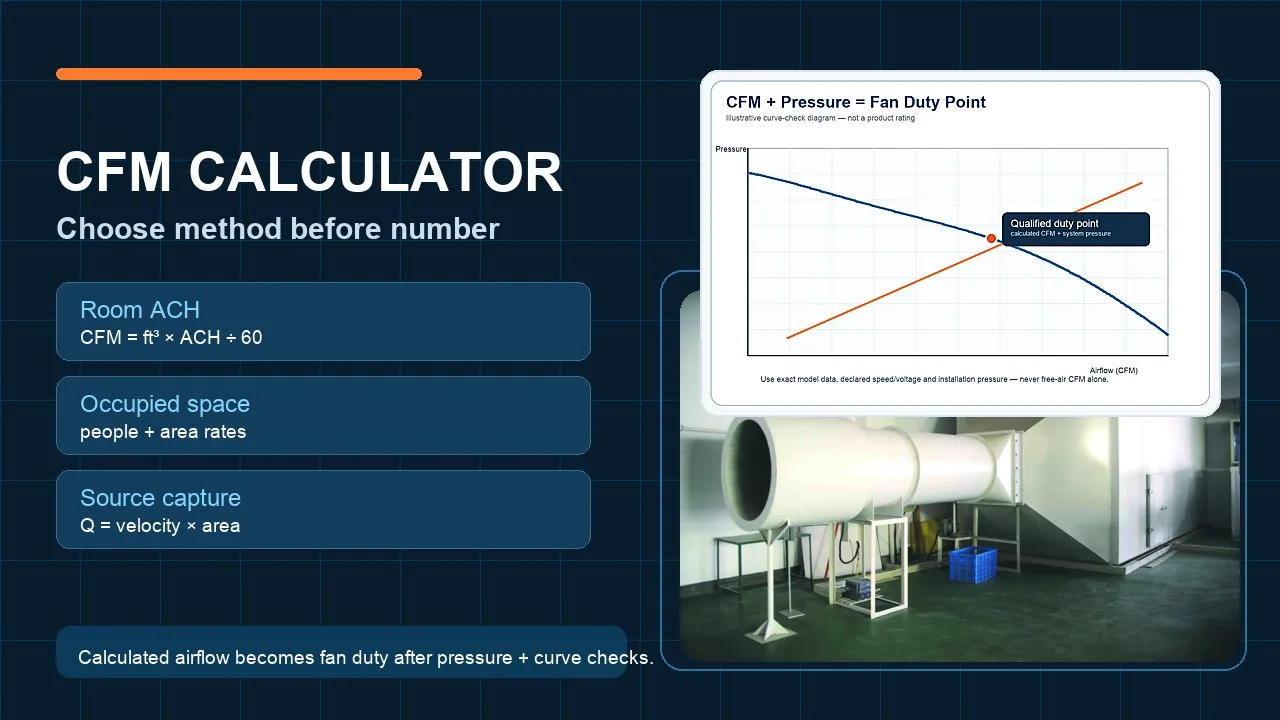
A first sensible-heat estimate is volume flow equals air-cooled heat divided by air density, specific heat, and the permitted air-temperature rise. Keep every term visible. For example, a teaching calculation may assign 500 kW to air cooling, use 1.18 kg/m³ density, 1.006 kJ/(kg·K), and a 12 K rise. The result is about 35.1 m³/s, or 126,000 m³/h.
Those values are arithmetic inputs, not a Longwell rating or a project recommendation. Replace them with the approved operating conditions and load distribution. Then reconcile the result with rack demand, leakage, installed equipment limits, and simultaneous normal and failure states. A correct heat balance is the beginning of the airflow budget, not a completed fan schedule.
Trace one cold route and one hot return route
Supply air should reach equipment intakes, cross the IT load once, and leave through a defined return path. Rack orientation, blanking panels, cable openings, containment, diffusers, and return placement all affect that route. Inspect the most loaded and geometrically difficult locations rather than assuming a balanced room average.
Recirculation sends hot exhaust back to an inlet. Bypass sends cold supply air back to the cooling unit without removing IT heat. These faults require different corrections. Seal the shortcut, align delivery with rack demand, and verify containment leakage before raising fan speed; more airflow can otherwise strengthen the wrong route.
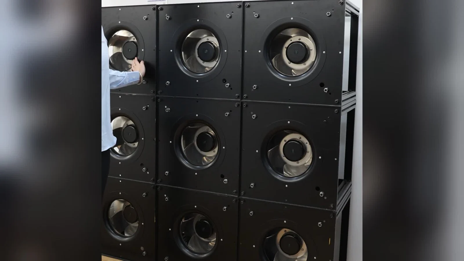
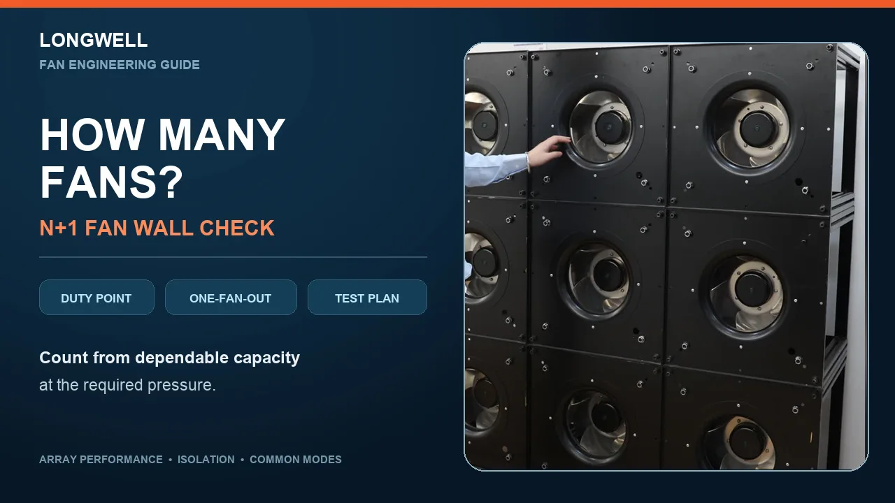
The pictured array is visible hardware and service context only. It does not establish airflow, pressure, sound, redundancy, control response, or suitability for the teaching calculation.
Join airflow to a pressure ledger and verified curves
At the required flow, list each resistance inside the declared system boundary: filter condition, coil, plenum, distribution path, containment, rack path, and return. Record clean, loaded, maintenance, and abnormal configurations. Do not add one unexplained percentage to cover unrelated uncertainties.
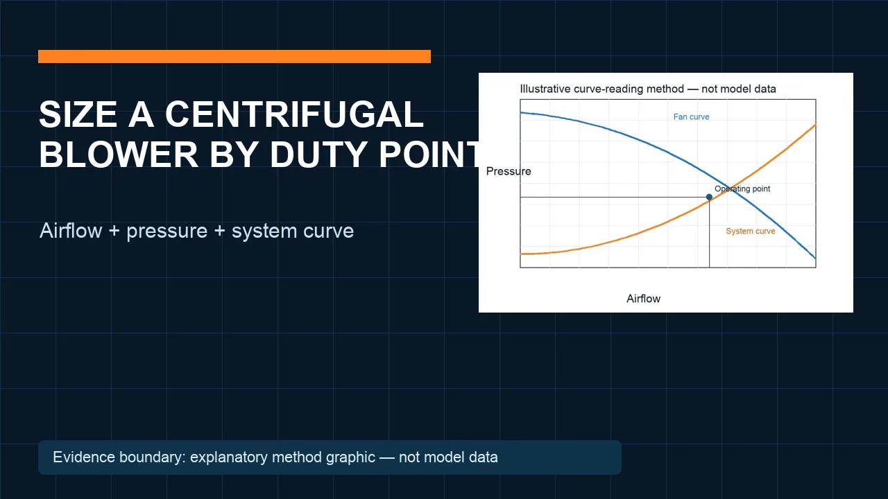
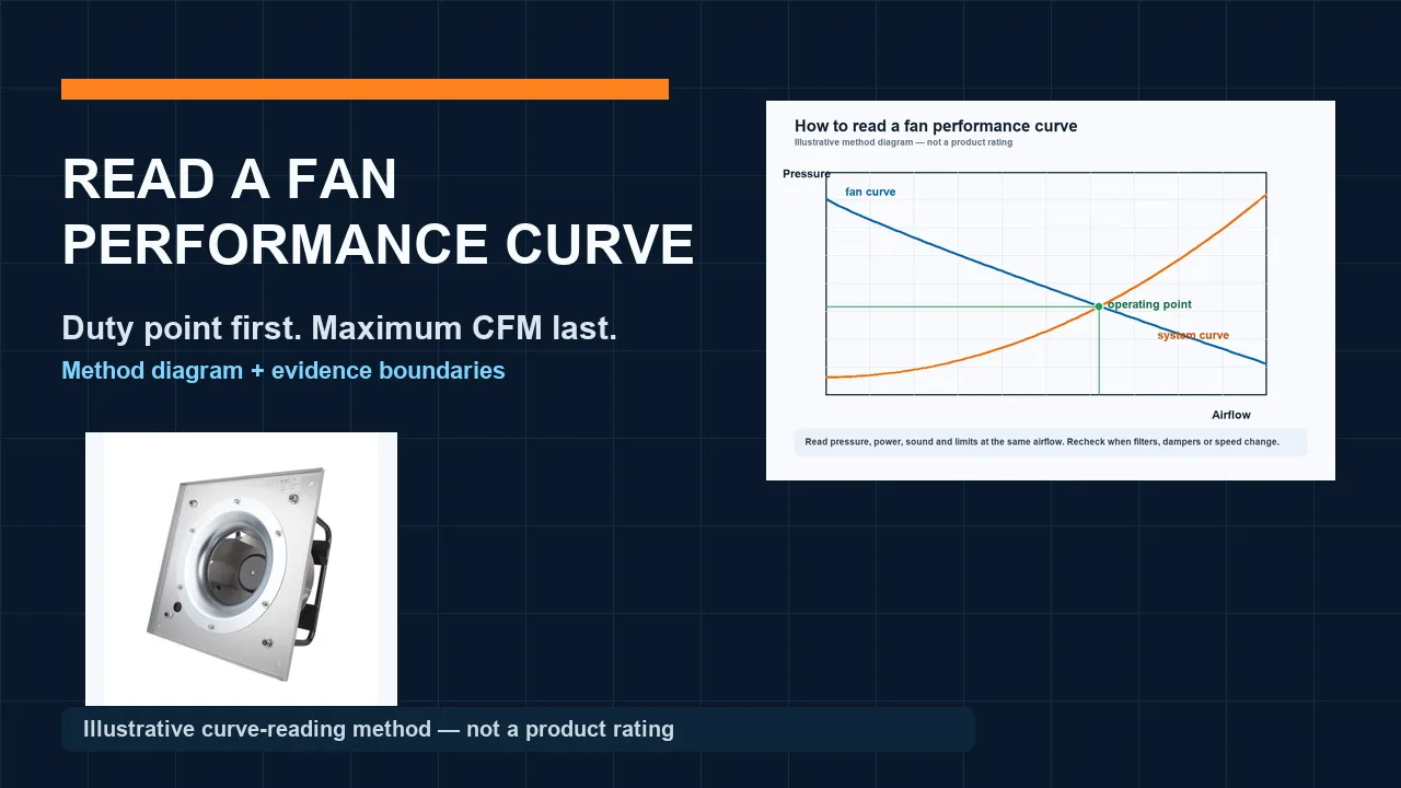
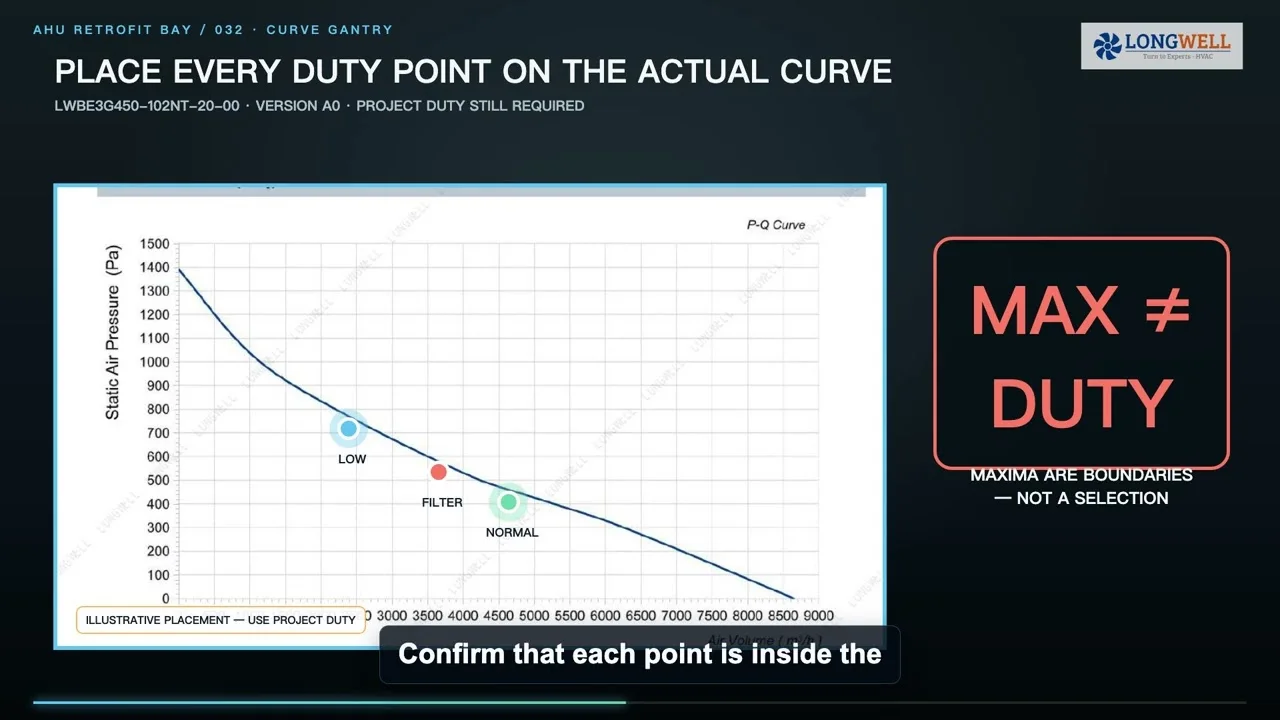
Place each duty on the exact fan and system curves using a consistent static- or total-pressure definition. The operating point is their intersection, not the free-air maximum and not an isolated pressure number. The fan-curve operating-point guide explains that comparison method.
Recalculate the common point with one module unavailable
For an array, determine the normal sharing point and then remove the approved module from service. Account for isolation, leakage, or reverse flow through its bay. The remaining modules must find a new common-pressure operating point on their exact curves. Check speed, electrical input, current, stable range, sound boundary, and controller limits instead of assuming that equal arithmetic sharing continues.
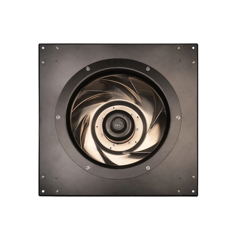
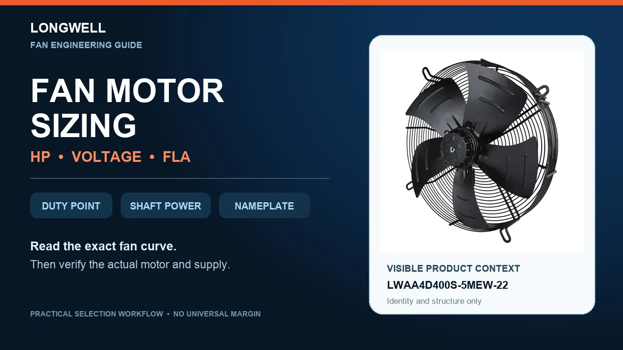
The photographed EC module shows visible construction only. It is not an identity claim for the project and cannot prove a curve, control protocol, certification, installed compatibility, or one-module-out result. The EC plug fan family is an architecture-discovery route; approval still requires the exact model, suffix, revision, curve, drawing, and control documents.
Script the failure test around server-inlet response
Use an approved and safe failure stimulus. Time-stamp the command, detection, alarm, fan redistribution, pressure response, hottest server-inlet rise, peak, stabilization, and recovery. Capture fan speed and current, cooling-unit state, containment differential pressure, representative inlet temperatures, and any override. Keep the IT load and test boundary documented so a later result can be compared fairly.
Separate failure classes. One fan module, one complete cooling unit, a controller or communications fault, and an electrical-path fault may have different shared causes and thermal consequences. Planned maintenance creates another configuration. N+1 fan capacity does not automatically prove resilience of cooling units, power, sensors, controls, or the air route.
Release only the scenario that the evidence actually passed
The release record should contain the rack-load map, air-cooled fraction, inlet envelope, airflow equation and density basis, cold and hot routes, leakage assumptions, pressure ledger, exact curve revisions, normal and failed operating points, control sequence, power path, sensor locations, test stimulus, time-series evidence, and recovery criteria.
Write the conclusion narrowly: which equipment identity, load, ambient condition, maintenance state, and failure class passed which inlet boundary. If the hottest representative inlet, electrical limit, stable curve range, or recovery rule fails, hold approval and correct the air route, capacity, control logic, or redundancy architecture. That is a defensible redundancy decision; a fan count by itself is not.