Short answer: select a cleanroom fan filter unit at two declared duties: the initial filter condition and the project’s planned loaded-filter endpoint. The fan must reach both points inside its documented speed, input, temperature, sound, and control limits. A free-air maximum does not answer that question.
That distinction prevents a common procurement failure. The fan, filter, casing, discharge face, controls, and ceiling return path form one system, yet quotations often describe only one component. The method below turns the complete module into a reviewable duty before anyone argues about fan diameter or motor type.
Write the complete module boundary first
Trace the air path from the module inlet to the clean supply face. Include the prefilter if one is fitted, the fan section, high-efficiency filter, plenum, guard or diffuser, and any external resistance that belongs inside the supplier’s scope. Mark the pressure-measurement stations. Without that boundary, two suppliers can quote the same pressure while including different losses.
Lock the project inputs beside the sketch: module and grid dimensions, effective filter area, target airflow, initial and final filter resistance, available external pressure, electrical supply, control interface, sound target, ambient limits, service side, and the required test configuration. A supplier application page may help discovery, but the controlled project schedule remains the authority for the actual duty.
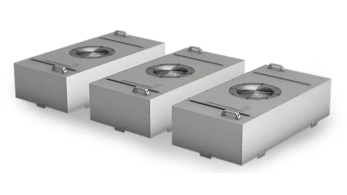
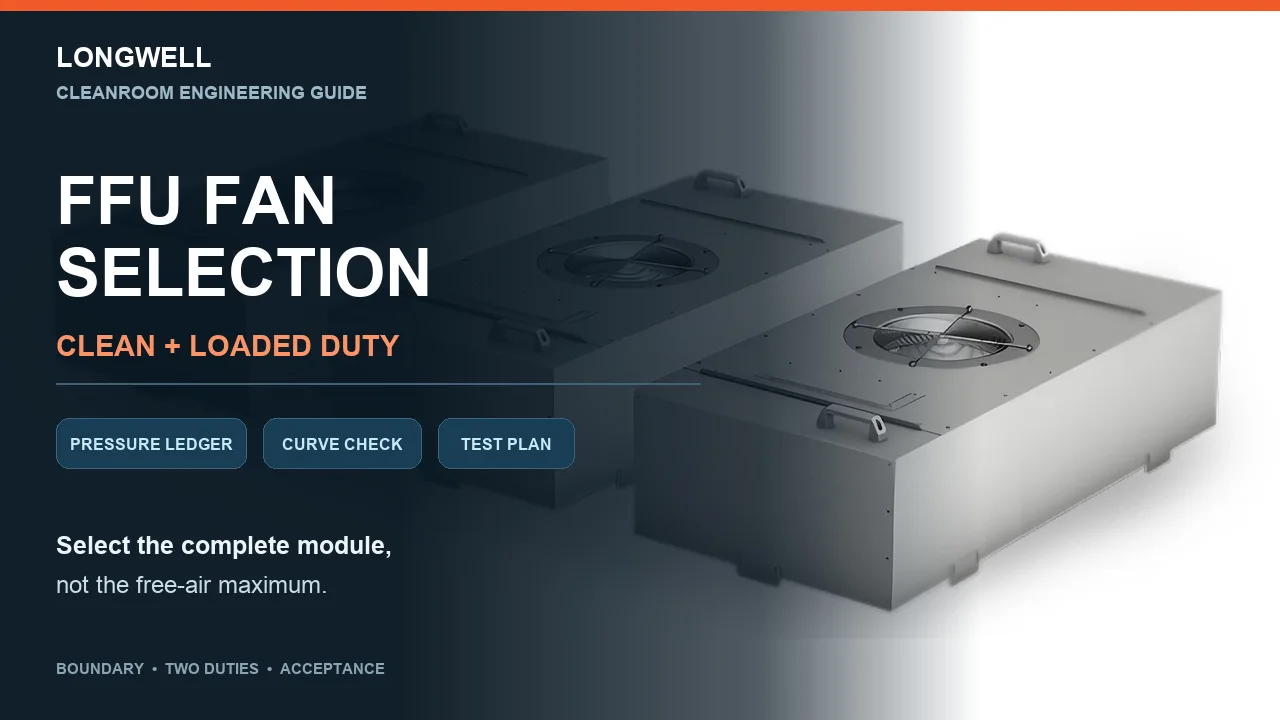
The real Longwell FFU housings above show exterior and inlet layout only. The photograph does not establish airflow, pressure, filter class, sound, efficiency, certification, controls, or suitability for a particular cleanroom.
Convert the room requirement into module airflow
For a defined active area, the screening calculation is straightforward: module airflow = effective face area × project-specified face velocity. Use consistent units and keep gross frame dimensions separate from effective media area. Then map the active and inactive ceiling zones and state how many modules operate in each control group.
Do not borrow a universal face-velocity number from another cleanroom. The owner’s process, airflow concept, occupancy state, leakage control, return path, and approved acceptance plan determine the target. Total volume is also incomplete by itself; the specification should define how velocity uniformity is measured across the face and how edge points are treated.
Build clean and loaded pressure ledgers
At the target airflow, list every resistance within the agreed boundary. A useful ledger has separate rows for the prefilter, initial high-efficiency filter, casing and internal components, discharge element, and project-specific external resistance. Record the source, revision, airflow, air condition, and test or calculation basis for each entry rather than mixing values copied from unrelated documents.
Duplicate the ledger and replace the initial filter resistance with the project’s planned final value. Those two totals are the clean and loaded system duties. If a supplier cannot state which filter condition a quoted point represents, the point is not ready for comparison.
Check both points on one controlled fan envelope
Plot the clean and loaded duties on the exact fan performance envelope for the proposed fan, speed range, air density, and installation boundary. The operating point is where the fan curve and the relevant system curve meet. Our fan curve guide explains the pressure, airflow, speed, power, and revision fields that must stay together.
At each endpoint, check available speed, electrical input, current, electronics and motor limits, stable operation, and the project sound requirement. Then review the path between them. A fan that reaches the initial point but has no documented route to the loaded point is not a loaded-filter selection.
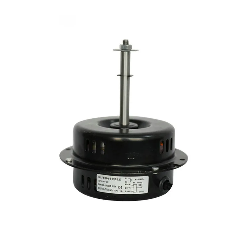
The image above is a real Longwell LWFU-AC300S family motor-and-impeller view from the authorized NAS library. It provides family identity and visible construction context only. The suffix, curve, electrical details, controller, and document revision still need to match the quotation. Browse the broader EC plug-fan family only after the complete duty and interface are fixed.
Review controls, service, and the installed array
Document the command signal, feedback, addressing or grouping, fault behavior, alarm handoff, and response after a module becomes unavailable. Do not assume constant-airflow control, a communications protocol, or automatic compensation from the motor technology alone; verify the exact controller and system logic.
Service constraints can change the shortlist. Confirm room-side or top-side access, filter-removal direction, gasket inspection, lifting and removal space, electrical isolation, and the treatment of a failed opening. Also check heat and sound at both operating endpoints. Best-case catalogue values do not describe a ceiling running at a different speed and resistance.
Make the acceptance plan part of the RFQ
Agree on what will be tested at module level and what will be verified after installation. Depending on the project, the record may include volumetric airflow, available external static pressure, filter-face velocity uniformity, electrical parameters, sound, housing vibration, filter integrity, control response, alarms, and a higher-resistance operating check. Name the method, instruments, locations, tolerances, occupancy state, and configuration.
The final review pack should contain the boundary sketch, both pressure ledgers, effective area and airflow calculation, exact fan and filter document revisions, clean and loaded operating points, electrical and control interfaces, service side, operating limits, and acceptance plan. Send the controlled inputs to engineering rather than submitting only a free-air target.