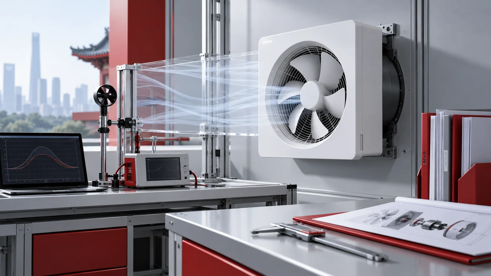
Choosing a cooling fan for a battery energy storage system should not begin with a catalog page. The useful starting point is the job the assembled air path must perform: where heat enters, where it leaves, how much resistance the air encounters, and how the controls respond as operating conditions change.
That distinction prevents a common selection error. A fan can look suitable at free air yet miss the required airflow after filters, coils, louvers, guards, ducts and enclosure losses are included. The video and guide below turn the discussion into a duty definition that an engineer, fan supplier and commissioning team can all check.
Start with the BESS operating modes
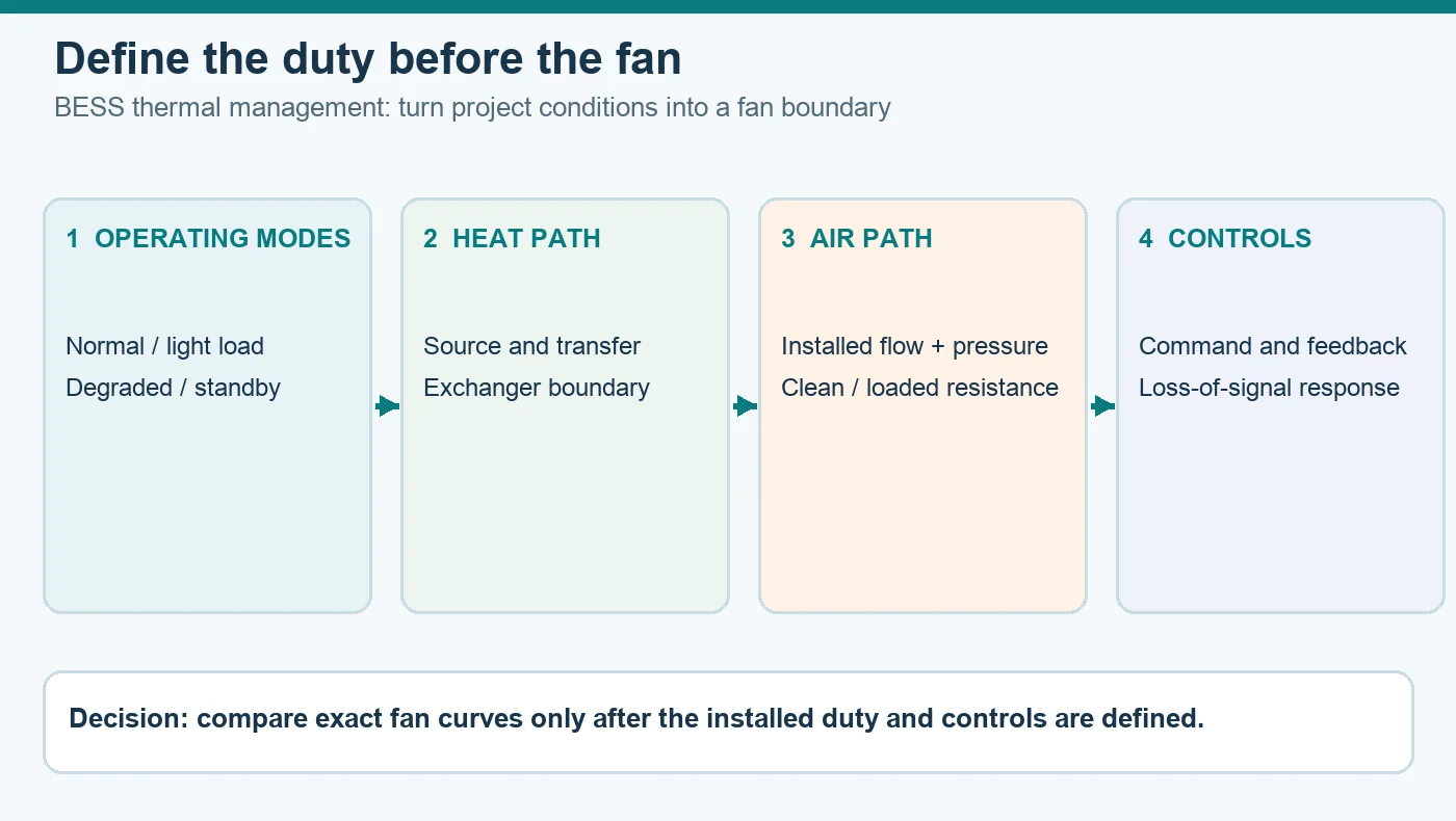
A single design point rarely describes the whole system. List the modes the project actually permits: normal heat rejection, light-load circulation, standby, charging or discharging transients, maintenance, loss of a cooling component and any project-defined abnormal response. For each mode, record the heat source, permitted temperature range, active air path and expected fan state.
Do not merge normal thermal management with emergency ventilation. The latter belongs to the project hazard analysis, battery chemistry, enclosure design and applicable authority requirements. A cooling-fan choice cannot establish an emergency sequence by itself, and no fan should be presented as preventing thermal runaway.
Map heat to the real air path
Trace the thermal boundary before converting anything into airflow. Identify the cells or modules that generate heat, the cabinet surfaces and passages that transfer it, the heat exchanger or HVAC interface that rejects it, and the inlet and outlet paths the fan can actually influence. This reveals whether the fan serves cabinet circulation, an exchanger, a container loop or another defined subsystem.
Keep thermal load and fan airflow as separate quantities. The thermal model must state losses, gradients, allowable temperatures and uncertainty. Only then can the airflow requirement be tied to a physical boundary. For broader application context, Longwell’s BESS and EV fan platform shows the different places a fan may appear, but the project duty still governs the selection.
Define the installed fan duty point
At the fan boundary, specify required volume flow and pressure rise together. Add air density or the temperature and altitude basis, the inlet condition, the outlet condition and the complete system resistance. Filters, coils, heat exchangers, screens, dampers, guards, ducts and fouling all contribute to the pressure the fan must overcome.
The expected operating point is where the selected fan curve intersects the system curve. It is not the fan’s maximum airflow, maximum pressure or wheel diameter. Compare candidates on the same pressure definition, speed, density and test arrangement. If those conditions differ, the numbers do not describe the same job.
Use an operating envelope, not one attractive dot
A clean filter on a mild day is only one condition. Build system curves for the meaningful edges of operation: minimum and maximum ambient temperature, altitude or density, clean and loaded resistance, open and closed damper states, normal and degraded cooling paths, and the speed or control limits of the exact fan configuration.
Then check whether each curve intersects the fan curve in a stable and controllable region. Make margins visible and attach them to named uncertainties. An arbitrary oversizing factor can hide a weak estimate, shift the fan away from a useful operating region or create control problems at low demand.
Prove distribution, not only total airflow
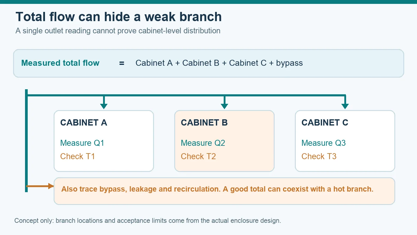
Total container airflow does not prove that every cabinet, module or exchanger face receives the intended flow. Cable trays, partitions, leakage, bypass, recirculation, short clearances and uneven resistance can leave one region under-served while the measured total still looks reasonable.
Define the measurement planes before hardware is frozen. A pressure map and temperature map can expose bypass and stagnant zones that a single outlet reading misses. When a backward-curved arrangement is appropriate to the pressure-flow task, the EC backward-curved fan family is a useful category to screen after the duty and space boundary are known.
Specify the motor, controls and failure behavior
The aerodynamic duty is only half of the specification. Record supply voltage and variation, input limits, command method, speed feedback, alarms, communication behavior, restart logic and the safe response to a lost signal. If a networked interface is required, verify the exact register map, firmware, electrical interface and isolation instead of assuming a generic protocol label proves compatibility.
Reliability must also be defined at system level. If redundancy is required, name the failed component, common power or control dependencies, backflow through an idle path, detection time, degraded capacity and recovery test. Two fans are not automatically an N+1 system. Every permitted staging combination needs a stable operating point.
Match construction to the actual environment
Temperature, humidity, condensation, dust, corrosion, water exposure, vibration, altitude and service access can change the acceptable fan construction. Ratings and certificates apply to exact configurations and stated installation conditions; they should not be transferred from a related model or a marketing illustration.
For a plenum-style installation where the surrounding unit forms part of the air path, Longwell’s EC plug fan family provides a product-family starting point. It is not a substitute for checking the selected model’s current curve, drawing, electrical data and environmental scope against the project.
Build the evidence pack before approval
A reviewable fan submission connects the exact offered model and configuration to performance curves, electrical data, dimensional drawings, materials, environmental ratings, sound data, control documentation, change control and traceable test records. Each document should carry a revision and a clear boundary so the design team can see what is current and what remains an assumption.
Keep exclusions explicit. A category image proves only visual identity. An illustration explains a relationship but does not prove performance. A nominal communication feature does not prove system integration. This discipline makes later substitutions and commissioning decisions easier to audit.
Commission the assembled BESS cooling system
Final validation happens in the installed system. Confirm rotation, guarding and electrical integrity; exercise commands, feedback and alarms; measure airflow or pressure at agreed planes; inspect temperature distribution, leakage and bypass; and repeat the checks across relevant clean, loaded, normal and degraded conditions.
Record instruments, locations, configurations and acceptance limits so the result can be reproduced. The right BESS cooling fan is not the product with the strongest headline. It is the exact configuration whose verified operating envelope, controls and installation boundary match the documented duty.
Choose the right dc cooling fan
Longwell manufactures 38 dc cooling fans in-house. Send airflow, static pressure and voltage — an engineer replies with a matching model, performance curve and price within one working day.