A whistle or hum tells you what to measure next; it does not identify a failed part by itself. The same audible tone can change with fan speed, duct geometry, motor control or a nearby machine. The useful decision is whether the sound follows running speed, an electrical condition, airflow resistance or structural vibration. Compare those conditions before buying a silencer or replacing a fan.
This guide follows the video’s diagnostic sequence. It offers general engineering checks, not a measured noise result, repair instruction or suitability claim for a particular LONGWELL model. If the sound arrives with rubbing, overheating, smoke, loose rotating parts or severe vibration, stop operation and follow the equipment’s safety procedure.
Record the sound and the operating condition together
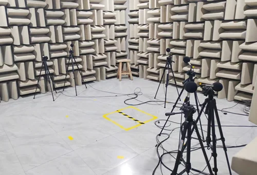
Capture a short recording from a repeatable, safe location. Note fan model and suffix, running speed, supply and drive mode, damper or filter state, airflow and pressure if available, and whether other equipment is operating. A phone clip can preserve the complaint and timing, but its microphone and automatic gain are not a calibrated sound-level or frequency measurement. If a tone matters to a specification, use an appropriate instrument and measurement method.
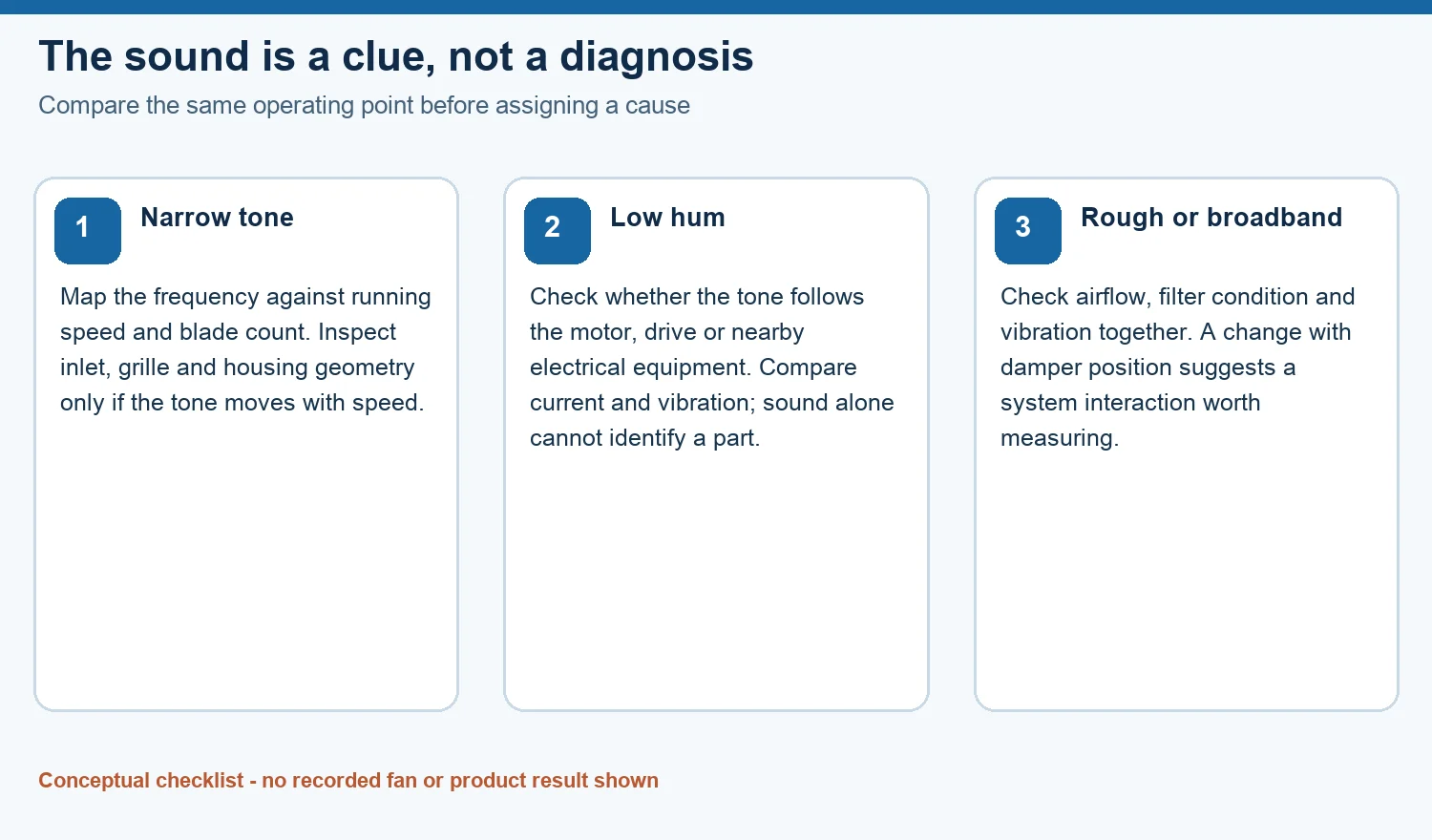
Ask whether the sound appears at startup, at one speed band, with a particular damper position, or at every duty point. If a tone moves in frequency when speed changes, a rotation-related or aerodynamic source becomes worth testing. A steady hum that does not track speed suggests a different investigation. Neither observation is a final diagnosis: nearby drives, structural resonance and overlapping frequencies can confuse a quick listening test.
Test a whistle against the airflow path
A narrow whistle can be associated with a leak, grille, damper edge, inlet obstruction or blade interaction with stationary geometry. The correct location depends on the installed duct and fan. Observe whether the tone changes with speed and with an authorized, controlled change in system resistance. Compare the same microphone location and operating state each time. Do not reach into an inlet or remove a guard to “find” the noise while the rotor can turn.
If an inspection requires access, qualified personnel must follow the machine and site energy-control procedure. The OSHA hazardous-energy program guidance explains the need to control unexpected startup and stored energy during servicing. After isolation, inspect accessible seals, panels, grille edges, inlet clearances and foreign material against the exact equipment drawing. A gap seen on an unrelated fan or a generic photo does not establish the source in yours.
Separate a hum from the motor, drive and structure
Low-frequency hum can come from an electrical component, a motor or drive, or a structure excited by the rotating system. A frequency close to line-related components can support an electrical hypothesis, but it is not a motor-failure verdict. Note the supply frequency and control method, then compare current, speed and vibration with the noise. Variable-frequency drives add switching and control behavior that a simple “100 or 120 Hz means the motor” rule misses.
Check whether the sound persists when the specific fan is safely stopped under the approved procedure and other equipment remains on. Then identify which equipment is actually audible before opening a fan housing. If the hum appears with no rotation or with abnormal current or heat, stop and have qualified electrical personnel investigate. Do not infer a seized bearing or failed capacitor from sound alone.
Use frequency to narrow the next inspection
Blade-pass frequency is blade count multiplied by revolutions per second. For an illustrative eight-blade rotor at 900 rpm, rotation is 15 Hz and blade passing is 120 Hz. A measured 120 Hz peak could fit blade/stationary-part interaction, but other sources may occupy the same band. Match the peak to actual RPM and blade count, and test whether it shifts as predicted when speed changes. The AMCA fan-noise guidance describes blade-pass tones and resonance as distinct mechanisms.
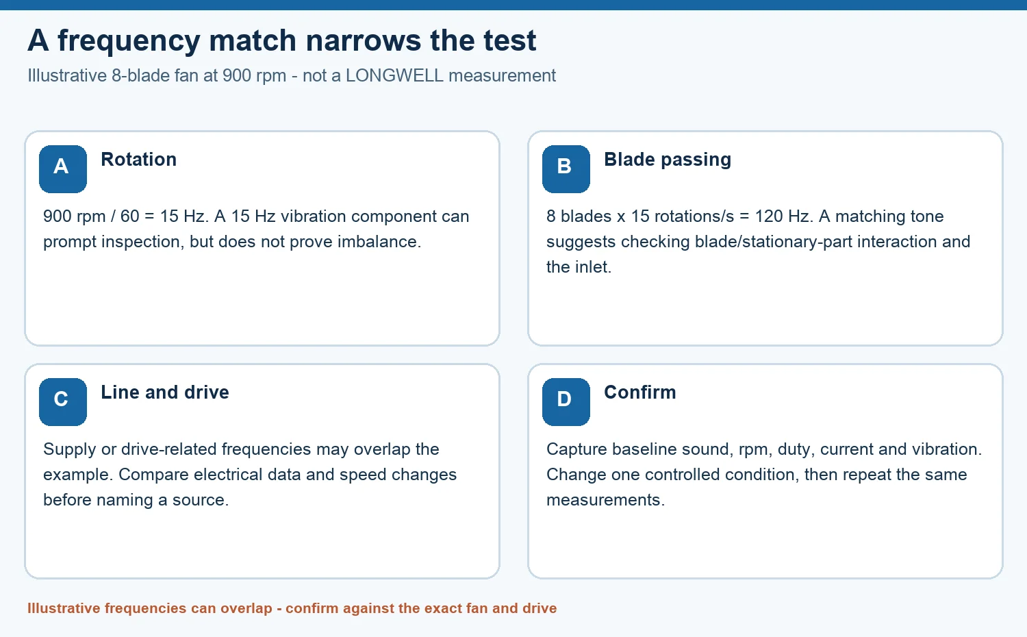
LONGWELL’s blade-pass calculator is useful for estimating where to look in a spectrum. Treat its output as a frequency hypothesis rather than proof of a defect. A peak at one times rotation can also arise from several mechanical or structural conditions; it does not prove wheel imbalance. If the tone is narrow and speed-sensitive, inspect inlet geometry, clearances and stationary parts under the exact fan’s service instructions.
Check broadband sound and the measurement path
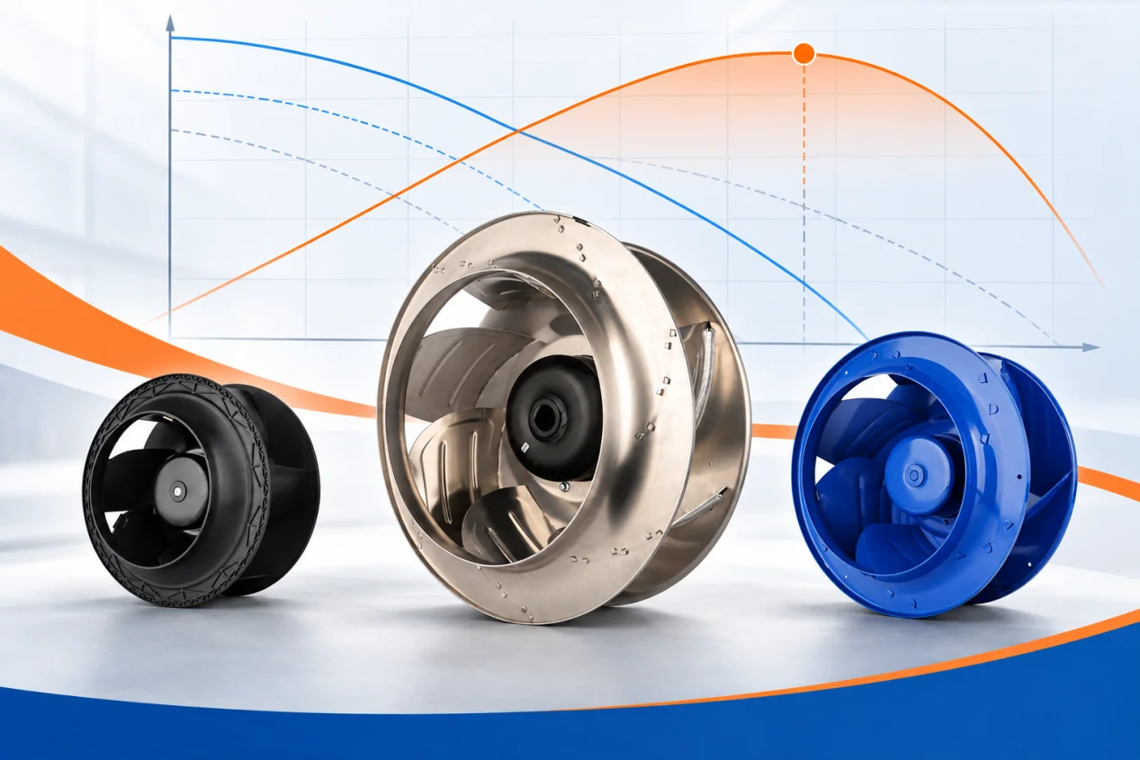
Rough broadband noise may change with turbulence, inlet distortion, filters, flow restriction or the fan operating point. A sudden change can also result from contact or a mechanical problem. Measure the pressure and airflow condition where practical, and compare it with the fan curve and the system’s normal baseline. A roar alone cannot prove a blocked filter or an undersized duct, and moving a damper merely to silence a tone can compromise the required duty.
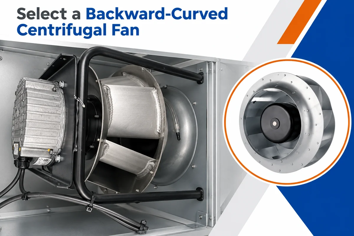
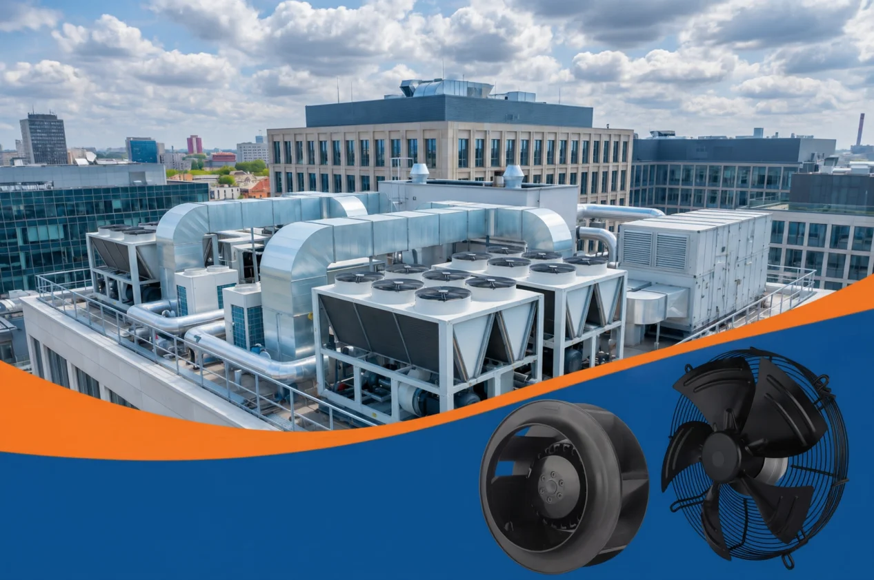
Airborne sound and structure-borne vibration take different paths. A duct lining or attenuator can change transmitted airborne sound, while a vibrating casing or support may need mechanical investigation. Test the path before selecting a remedy. LONGWELL’s centrifugal fan family and duct fan family show available construction types only; neither page establishes that any model will meet the noise target or replace the installed unit without exact duty and acoustic evidence.
Change one condition and verify the result
Make a short hypothesis list from the recording and operating data. Select the least invasive safe check that can separate the candidates: a repeatable speed sweep, filter-pressure comparison, vibration measurement at defined locations, electrical observation or isolated visual inspection. Change one condition at a time under the equipment procedure and document what happened. Restoring the original condition is part of the comparison. Avoid treating a quieter subjective impression as a measured sound-power improvement.
For an engineering review, send the fan and motor model with suffix, drawing revision, application, RPM range, airflow and pressure duty, supply and control details, recordings from known positions, measured spectrum or octave-band data if available, vibration observations and the specific condition that changes the noise. Include the noise limit and test method if one applies. That package lets a team decide whether the next step is a system correction, a controlled acoustic test, a mechanical inspection or a different fan selection.
Need to review a fan-noise problem? Send the exact unit details and your observations to sales@longwellfans.com.