What the air curtain OEM specified
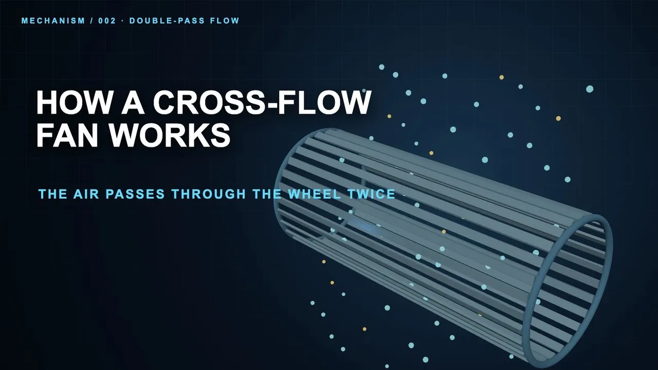
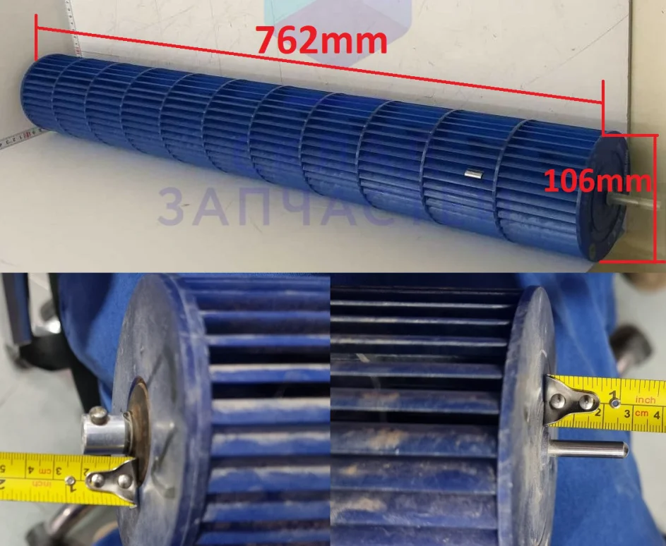
A leading HVAC OEM needed a plastic cross-flow impeller for a new line of premium air curtains. The part is 762mm long and 107mm across.
They sent core dimensions from a legacy design, plus a target airflow of roughly 1700 to 2550 m3/h. However, the dimensions were the easy half.
The requirement that actually mattered
These air curtains sit above doorways in high-end retail and hospitality. Consequently vibration and noise are not niceties here. In effect they are the product.
- First, radial runout no more than 0.7mm, with axial runout under 0.6mm.
- Second, dynamic balance better than 0.3g measured at 1200 RPM.
- Next, no deformation or odd noise at a 1600 RPM test speed.
- Finally, a durable lightweight plastic suitable for continuous running.
In truth that 0.3g figure is the whole brief in one number. Below it, nobody standing in the doorway feels a thing.
The enquiry came from their engineering team. Moreover they had their own motor and housing, and wanted a supplier who could turn targets into a production part.
Making the plastic cross-flow impeller
Essentially the work here was turning targets into a drawing we could make and check.
Aluminum was considered and rejected
An extruded aluminum impeller is stiffer, which helps over 762mm. Even so, we turned it down.
Aluminum adds weight, steps and cost. Furthermore a metal part this long risks resonant noise. That is the one failure this product cannot afford.
The material we chose instead
So we specified AS with 30% glass fiber. The glass content stops the part flexing across 762mm at 1600 RPM. Meanwhile it holds its shape well and costs little at volume.
It is also far lighter than metal. A lighter rotor is easier to balance, and gentler on the customer bearings.
Why the blades are welded, not fastened
Notably, the drawing calls for the blades to be joined to the end rings by ultrasonic welding.
That makes a molecular bond rather than a mechanical joint. Screws loosen under vibration. Meanwhile adhesives degrade with heat cycling. Either one shifts the mass slightly, and a 0.3g spec has no room for slight.
Consequently the welded plastic cross-flow impeller behaves as one solid piece for its whole service life.
Balancing along the length
A part this long cannot be balanced at one point. Instead we balance at several stations along its length, using at most three small clips to hit the target.
Here the approved drawing captures all of it. Consequently every unit meets the same noise and vibration standard as the first article.
Technical Specifications
The runout and balance rows below are the real specification. By contrast, the dimensions were never the hard part.
| Parameter | Value |
|---|---|
| Model Number | LWPI-Φ107X762-01 |
| Impeller Type | Cross Flow Impeller |
| Diameter | 107 mm |
| Length | 762 mm (±2 mm tolerance) |
| Material | AS+GF30% (Acrylonitrile Styrene + 30% Glass Fiber) |
| Rotation | Counter-Clockwise (CCW) |
| Max Speed (Operational Test) | 1600 RPM |
| Dynamic Balance Specification | ≤ 0.3g @ 1200 RPM |
| Radial Runout Tolerance | < 0.7 mm |
| Axial Runout Tolerance | < 0.6 mm |
| Shaft Runout Tolerance | < 0.2 mm |
| Reference Airflow (Application Target) | 1000 – 1500 CFM |
Technical Documentation
Following the Review/Approved and Archived stages, the following final documents were delivered to the customer and filed, confirming the design for mass production.
LWPI-Φ107X762-01.pdf
The final engineering drawing contains all dimensional tolerances, material specifications, and quality control requirements, used by OEM engineers for system integration and by quality teams for incoming inspection.

The primary technical drawing view shows the impeller’s key dimensions, counter-clockwise rotation, and shaft end detail, essential for motor and housing design.

A photo of the finished product illustrates the final blue color, blade arrangement, and the shaft assembly with balancing clips visible, confirming the production output against the drawing.
Why they sourced the component here
OEMs come to us for a custom plastic cross-flow impeller when the catalog has no answer.
- Custom parts in 90 days. This impeller is a non-standard size with a non-standard performance profile. A production-ready specification and tooling came out of our 90-day NPI cycle, against the 12 to 18 months European suppliers typically quote.
- Advanced process, sensible cost. Glass-filled plastic plus in-house ultrasonic welding gave the rigidity a 762mm span needs, without the weight and the machining time a metal impeller would have added.
- Quality you can verify. Their brand rests on quiet operation, so a balance figure needs proof rather than intent. Our ISO 9001 line and documented specifications show that every impeller meets the 0.3g target.
- Component supply, not a bundle. This was a plastic cross-flow impeller on its own. They kept their motor and housing, while we supplied the part they did not want to develop.
Browse our cross flow fan range, or the cross flow impeller section. Balance grades come from ISO 21940.
Questions about custom impellers
How long does a custom impeller project take?
Our standard NPI timeline is 90 days from drawing approval to first article. That covers tooling, inspection samples and full validation against every line on the drawing, balance included. In practice tooling is the long pole, not the molding.
Can you make the same impeller in aluminum?
Yes, and we do it often. This plastic cross-flow impeller was optimized for the best balance of cost, weight and rigidity up to 1600 RPM. However, extruded aluminum gives better structural integrity and a wider temperature range. That suits industrial drying or electronics cooling. Send us your requirements and we will compare both.
Does ultrasonic welding hold up over time?
It does, and that is the reason for choosing it. The weld forms a permanent bond between blades and end rings, so the impeller behaves as one piece. Mechanical fasteners loosen under vibration and adhesives degrade with thermal cycling, and either one shifts the balance. The welded joint keeps the 0.3g figure for the life of the part.
Why is length such a problem for balancing?
Because a long rotor can be balanced at each end and still bend in the middle. Imbalance spread along the span shows up as a bending mode rather than a simple out-of-round. Consequently correcting it at one plane does nothing. That is why we balance at several stations, and why stiffness mattered so much here.
Technical Documentation & Resources

Need the same thing for your own unit?
Give us the numbers and the envelope, and you get a shortlist rather than a catalog. Meanwhile custom spec sheets and samples run to 90 days. Since 1990 Longwell has supplied EC fans and blowers to OEMs in HVAC, cold chain, data center and industrial markets.
🏆 ISO 9001 / ISO 14001 / ISO 45001 | CE (TÜV) | UL/ETL | ATEX Zone 21/22 | AMCA 210/211 / ISO 5801 tested
Choose the right plastic cross flow impeller
Longwell manufactures 42 plastic cross flow impellers in-house. Send airflow, static pressure and voltage — an engineer replies with a matching model, performance curve and price within one working day.