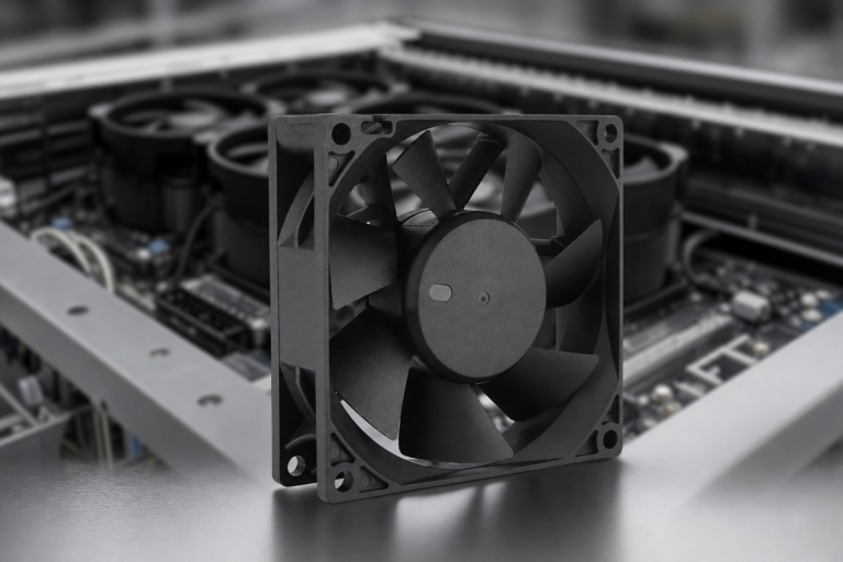
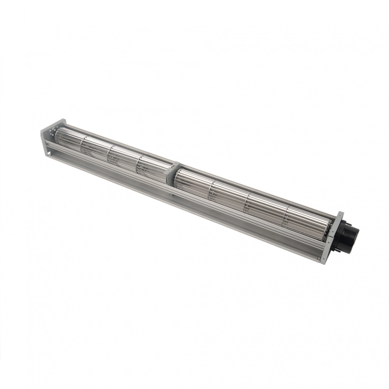
The same fan, ordered in both directions
A commercial cooling customer ordered matched 185mm axial fans in suction and blowing variants, for a push-pull fan configuration in a ventilation array. In this arrangement, one fan drives air into the loop, and its partner draws it out the other side.
In fact, the request explicitly asked for two mirror-spec documents, one per orientation. That detail is the story.
The shared envelope
- First, 742 m3/h peak airflow from each fan, inside a 58.5mm installation depth.
- Next, 220 VAC tolerating 198 to 242 V, at 50 or 60 Hz.
- Meanwhile -30C to +60C ambient, S1 continuous duty, 52 dB(A) at 60 Hz.
- Finally, 30,000 hours maintenance-free at 40C, with CE and EN 60335-1.
Why anyone builds a push-pull loop
A single fan fighting a resistive path does all the work from one end. Consequently, the pressure it can develop caps the airflow.
A push-pull fan configuration splits that work. The upstream fan pressurises, the downstream fan de-pressurises, and the two pressure contributions add across the resistance between them. The loop moves air neither fan could move alone.
A push-pull fan configuration needs two documents
At 58.5mm of depth, the motor choice narrowed immediately. First, we rejected a DC variant because the customer has no low-voltage bus, and an added AC/DC stage is a cost and a failure point serving nothing.
The impeller, and why seven blades
The direct-drive 220 V AC motor runs 2800 RPM to make 742 m3/h. However, at that speed a 5-blade design produced too much tonal noise, so a 7-blade sickle-profile impeller in cold-rolled steel took its place.
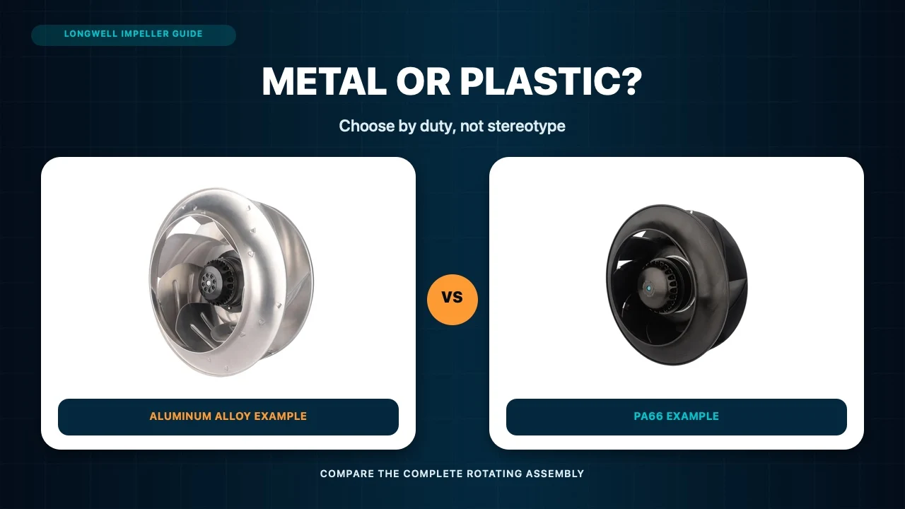
Why steel? Because -30C rules out the polymers that would otherwise serve. After all, a brittle blade and a cold-morning start are a bad combination.
Why two documents and not one
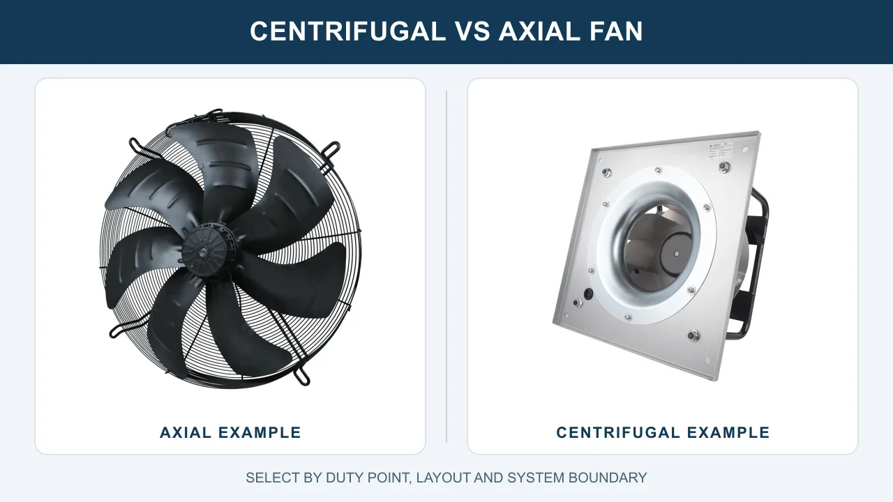
In a push-pull fan configuration, the suction fan and the blowing fan are not interchangeable units with an arrow flipped. The orientation changes which way air crosses the motor, where the wire exits sit relative to flow, and which face carries the guard.
So each variant carries its own specification: its own curve, its own noise figure, its own drawing. Otherwise, an installer holding the wrong sheet installs the wrong fan backwards with full confidence. That is why merging the sheets into one document saves nothing worth saving.
Matching matters more than performance
In a push-pull fan configuration, the two fans must be matched at the shared duty point. Surprisingly, a stronger fan on one side does not help. It moves the operating point of both, and it can push its partner into an unstable region of its curve.
For that reason, the customer bought the pair from one platform rather than mixing suppliers, and why both were tested to the same JB/T 10562 baseline and ISO 5801 methods.
The grid detail worth noticing
Lastly, dual-frequency rating is not a label. The same motor runs about 20% faster on 60 Hz, so airflow, noise and power all shift between grids. Accordingly, the 52 dB(A) figure of this push-pull fan configuration is quoted at 60 Hz, the louder case, which is the honest way round.
Technical Specifications
These figures describe both variants. What separates them is airflow direction, and that difference lives in two separate documents.
| Parameter | Value |
|---|---|
| Model Numbers | LWAA2E185S-7MNW-01 (Suction) / LWAA2E185B-7MNW-01 (Blowing) |
| Nominal Voltage | 220 VAC |
| Voltage Range | 198~242 VAC |
| Frequency | 50/60 Hz |
| Speed | 2400 / 2800 ±150 RPM |
| Power Input | 55 / 75 W ±15% |
| Airflow (Max) | 670 / 742 m³/h (394 / 436 CFM) ±15% |
| Noise Level (LpA) | 51 / 52 dB(A) |
| Operating Temperature | -30°C to +60°C |
| Dimensions | 185±3 mm diameter x 58.5±3 mm depth |
| Insulation Class | Class F |
| Protection Type | IP54 |
| Work System | S1 (Continuous) |
| Certifications | CE, RoHS, REACH |
Technical Documentation
Here the following engineering files were output during the final review phase for OEM integration:
- longwell-ac185-technical-doc-01.pdf – Contains the primary 220V performance curves and safety warnings required by system integrators.
- longwell-ac185-spec-sheet-02.docx – Editable specification draft for the customer’s internal procurement system.
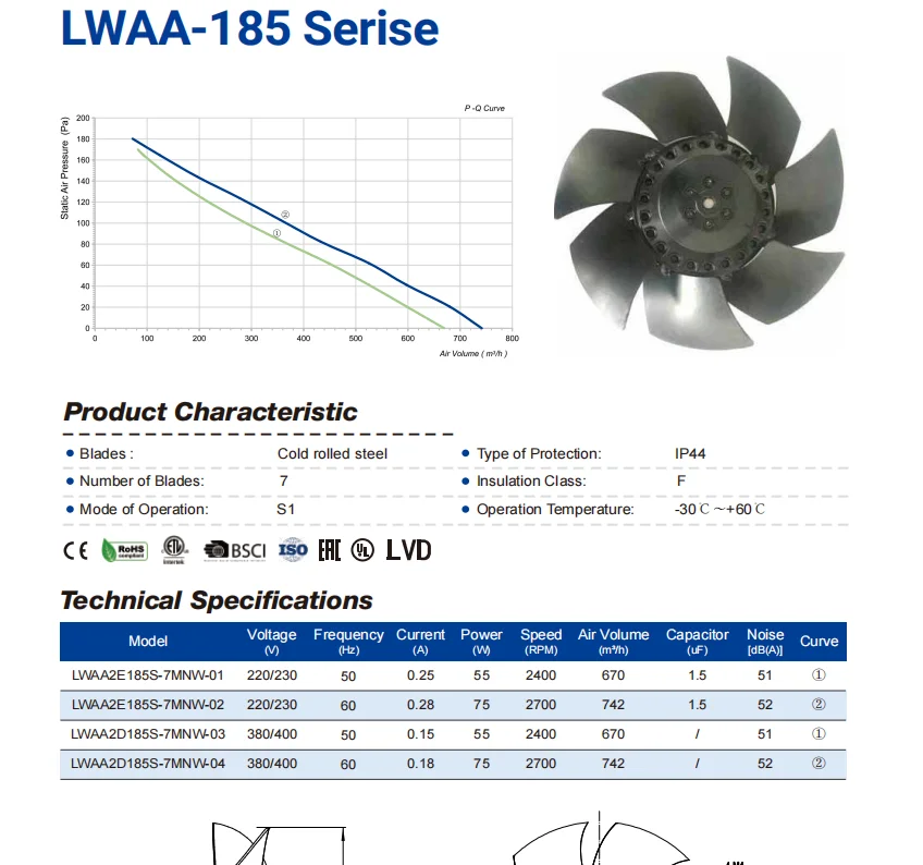 – Visual confirmation of the 7-blade sickle impeller design and central motor hub.
- longwell-ac185-spec-sheet-04.pdf – Approved engineering drawing showing the 58.5 mm depth and M4 mounting hole layout for mechanical designers.
- longwell-ac185-spec-sheet-05.docx – Final compliance checklist documenting GB12350 and JB/T 9101-1999 G6.3 balancing adherence.
Building a push-pull loop
If you are building a push-pull loop yourself, four decisions decide whether it works.
- Buy the pair as a pair. A push-pull fan configuration works when both fans sit at the same duty point. Order the suction and blowing variants together, from the same platform, and state that they will operate as a pair.
- Keep the two datasheets separate and label the installation. The variants look identical on a shelf. Mark the housings, mark the drawings, and make the orientation physically obvious, because a reversed fan in a loop cancels instead of adding.
- Specify the noise at the higher frequency. On a dual-frequency motor, 60 Hz is the louder, faster, hungrier case. A limit quoted at 50 Hz flatters every number by around 20%.
- Derate for the pair, not the fan. Two matched fans in series nearly double the pressure but not the airflow. Size the loop from the combined curve at your resistance, not from one fan’s free-air figure multiplied by two.
See our axial fans range, the AC axial fans section, or compact axial fans.
Questions about push-pull pairs
Does push-pull double the airflow?
No, it roughly doubles the available pressure. Consequently, airflow rises only as far as the system resistance allows with that extra pressure. On a lightly resistive path the second fan adds little; on a dense coil or filter bank it adds a great deal.
Can I use two identical fans instead of an S and B variant?
Physically you can mount one backwards. However, a fan reversed is not a fan designed to blow. Motor cooling, wire routing and guard position all assume one direction. In other words, the matched variants exist so each fan runs the way it was engineered to.
What happens if one fan in the pair fails?
The survivor keeps running at a worse operating point. Meanwhile the dead fan now acts as resistance in the path. Airflow falls well below half. Monitoring both fans, rather than trusting the pair, is the practical answer.
Why is the same fan louder on 60 Hz than 50 Hz?
Because an AC motor speed follows the supply frequency. So on 60 Hz the impeller turns about 20% faster, and aerodynamic noise rises steeply with tip speed. The same applies to power draw, which rises with the cube of speed.
Technical Documentation & Resources
Got a duty point you need matched?
Tell us the airflow, the pressure and the space you have. Then we mark your duty point on a tested curve and send the drawing back. Meanwhile samples and custom spec sheets take up to 90 days. Since 1990 we have supplied OEMs across HVAC, refrigeration and industry.
Browse Related Products:
🏆 ISO 9001 / ISO 14001 / ISO 45001 | CE (TÜV) | UL/ETL | ATEX Zone 21/22 | AMCA 210/211 / ISO 5801 tested
Choose the right axial fan
Longwell manufactures 1,086 axial fans in-house. Send airflow, static pressure and voltage — an engineer replies with a matching model, performance curve and price within one working day.