Fan motor sizing is not a CFM-to-horsepower shortcut. A defensible selection connects one qualified airflow-pressure duty point to the exact fan curve, the required shaft power, the permitted operating range, the drive arrangement, the available supply, and the actual motor nameplate. Skip any link in that chain and a precise-looking answer can still be wrong.
The practical rule is simple: read absorbed power from the correct fan curve whenever it is available. Use a calculation as a cross-check, then verify the motor rating, voltage, phase, frequency, full-load amps (FLA), starting method, and environmental limits for the exact ordered equipment. The worked numbers below teach the method; they are not a product rating or electrical-installation instruction.
Lock the fan duty before choosing a motor
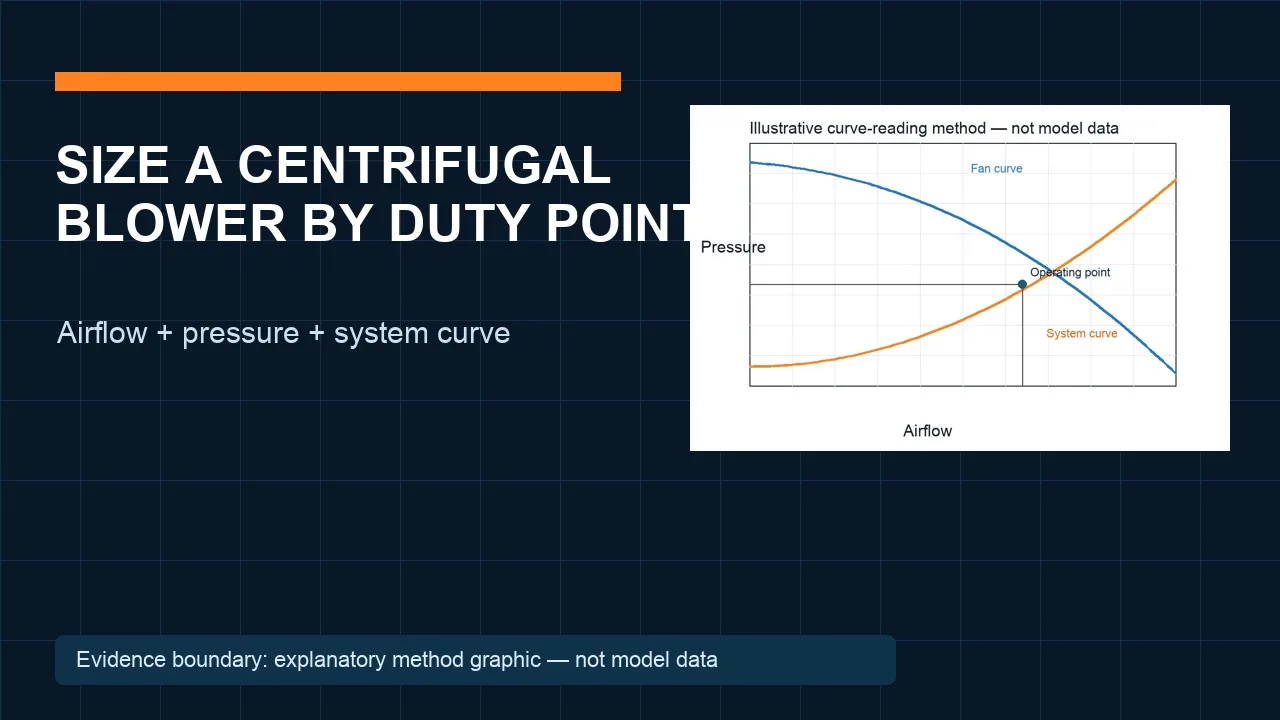
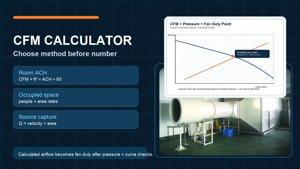
Start with airflow and pressure at the same operating condition. State whether the pressure is static or total, and record air density, speed, fan configuration, test arrangement, and curve revision. A free-air maximum or a motor wattage printed on a product listing does not define the installed duty.
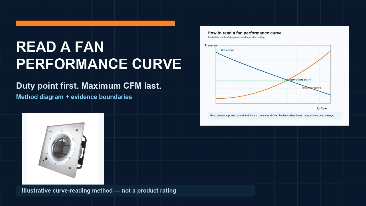
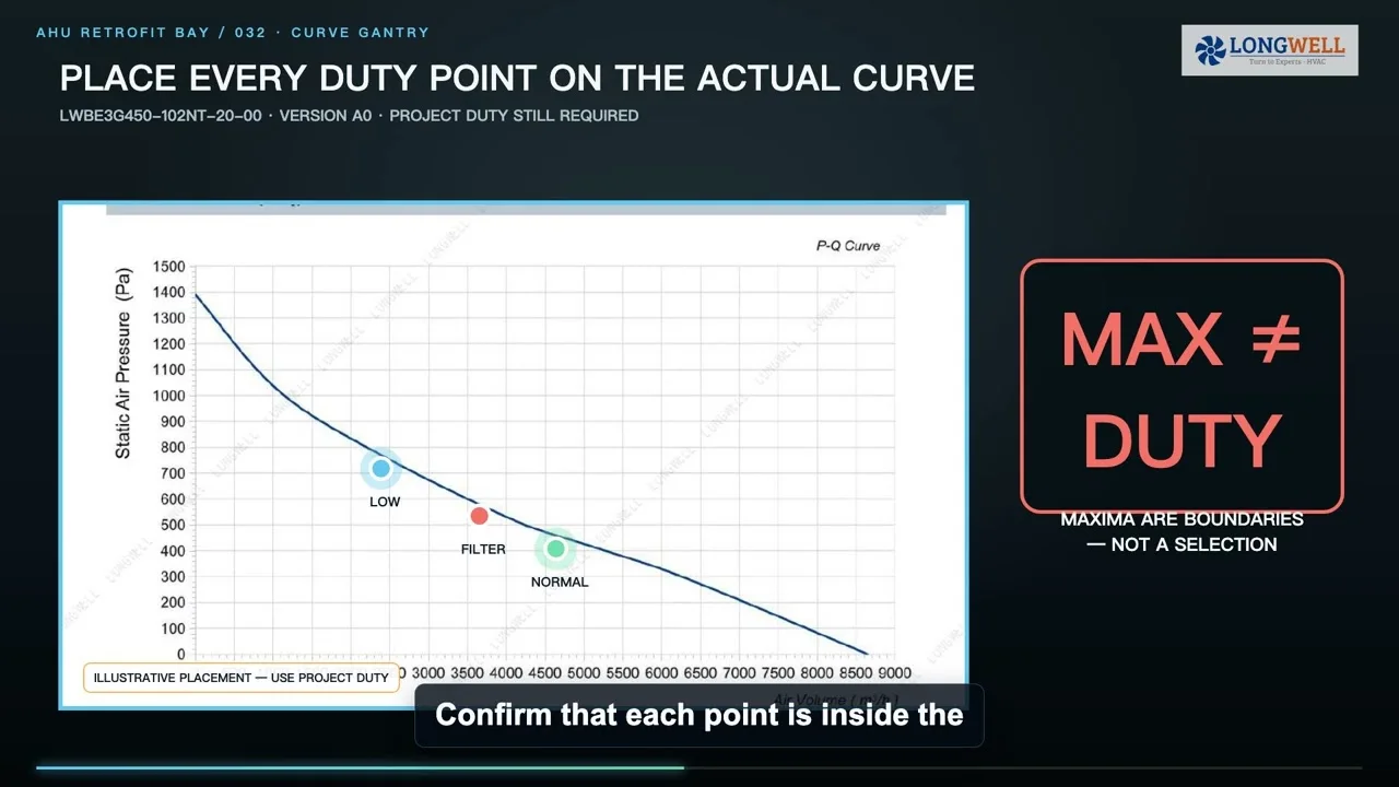
If the manufacturer curve includes absorbed or brake power, read that curve at every required point. Check the credible operating envelope as well as the nominal point: clean and final filter conditions, damper positions, allowed speed range, seasonal air density, and any process mode that changes resistance. Do not assume a generic power-curve shape from “axial,” “forward-curved,” or “backward-curved” alone; the exact tested assembly decides.
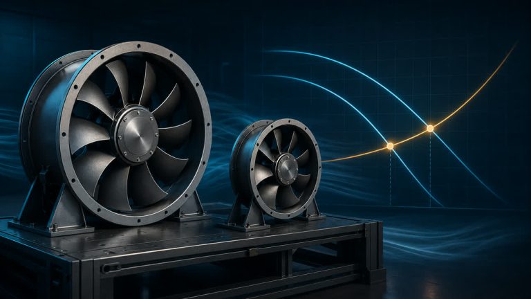
The fan curve guide explains how to keep airflow, pressure, speed, power, and the test boundary aligned before a motor is shortlisted.
Work the 1,000 CFM example without hiding assumptions
Suppose the teaching duty is 1,000 CFM at 2 in. wg static pressure and the matching fan static efficiency is 60 percent. Air horsepower is airflow multiplied by pressure and divided by 6,356, so the air power is 1,000 × 2 ÷ 6,356 = 0.315 hp. Dividing by 0.60 gives 0.524 hp at the fan shaft.
That 0.524 hp is valid only for the stated pressure and efficiency definitions. If the fan is belt driven, required motor output is fan shaft power divided by the documented drive efficiency; do not insert a universal belt-loss percentage. A direct-drive assembly has no belt stage, but its motor and controller limits still need checking.
A 0.75 hp motor, equal to about 0.559 kW of mechanical output, may enter the candidate list if the maximum required power remains below its continuous rating after the manufacturer’s documented derating and application checks. It is not an automatic selection. Starting torque, ambient temperature, altitude, duty, enclosure, and control method can change the answer.

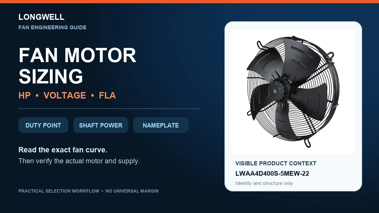
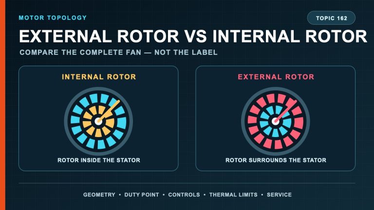
The pictured Longwell axial fan is exact variant LWAA4D400S-5MEW-22 from the authorized product library. It provides product-identity and visible-structure context only; the worked 1,000 CFM example is not its rating. Longwell’s AC axial fan family and external-rotor motor pages are family-discovery routes, not approval of a model for this example.
Keep motor output, electrical input, and supply separate
Horsepower or kilowatts on an induction-motor rating normally describe mechanical output. Electrical input is higher because motor losses must also be supplied. That is why converting 0.75 hp to 0.559 kW does not tell you the panel load.
Next, match voltage, phase, and frequency as one set. A motor marked for more than one voltage may require a specific lead connection, while nominal site voltage and rated motor voltage are not interchangeable without the manufacturer’s permitted range. Use the exact wiring diagram for the ordered suffix and confirm rotation, starter or VFD compatibility, and any required derating.
Use calculated current as a check, not as the nameplate
For a three-phase induction motor, a screening estimate is I = Pout ÷ (√3 × V × efficiency × power factor). Every input must refer to the same rated condition. An estimate based on assumed efficiency or power factor cannot replace the manufacturer’s FLA.
FLA is also not starting current, locked-rotor current, service-factor current, drive output current, or the current measured at a light operating point. Those values support different decisions. Conductor, overload, short-circuit, disconnect, starter, and drive selection must follow the actual markings, manufacturer instructions, the adopted code, and a qualified electrical professional.
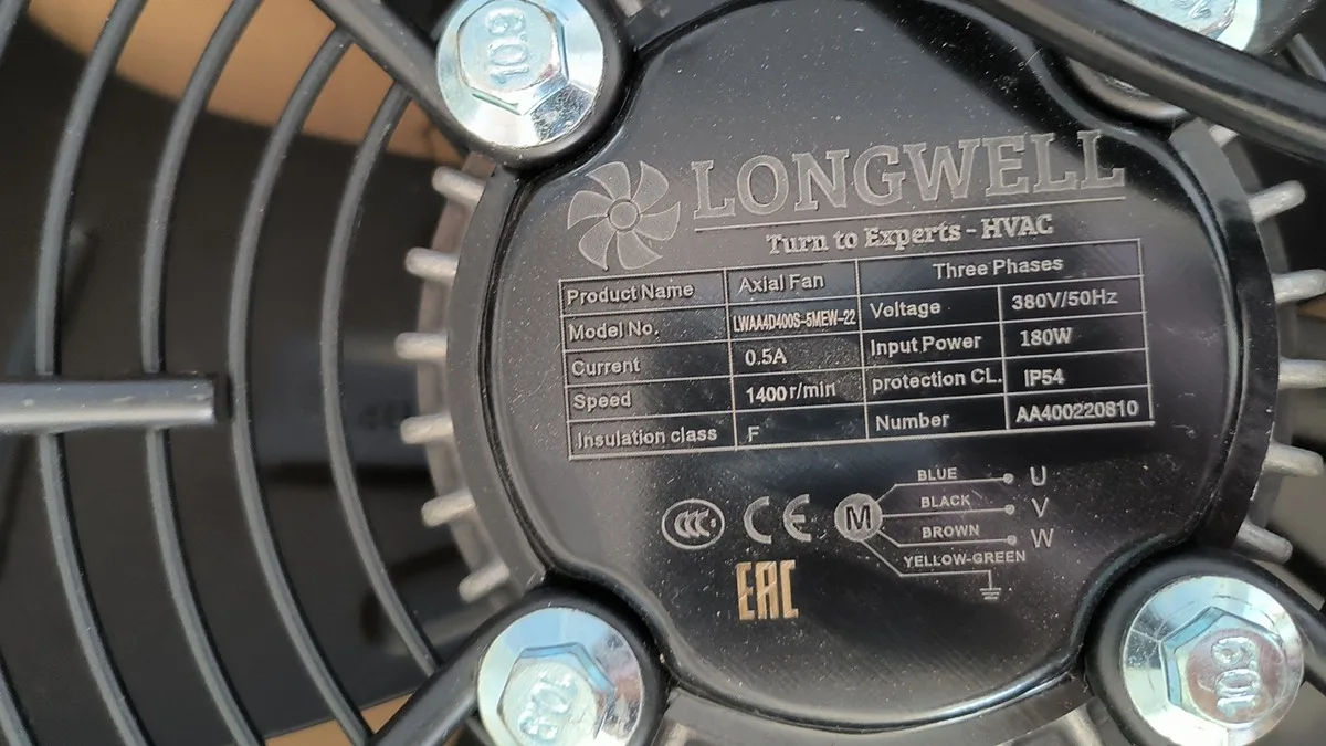
The close-up is the engraved label on the same LWAA4D400S-5MEW-22 variant. It visibly pairs 380 V / 50 Hz / three-phase supply with 180 W input power, 0.5 A, 1,400 r/min, IP54, and insulation class F. Those values belong only to that photographed variant and revision; they are not defaults for other axial fans or motors.
Put integrated EC fans on a separate paperwork path
An integrated EC fan is not selected by forcing its electronics into an induction-motor FLA table. Check the assembly’s declared input voltage, frequency, maximum input power and current, control interface, protection behavior, ambient limits, wiring document, and exact performance curve. “EC” does not prove one universal protection scheme or eliminate project-specific electrical review.
Issue an RFQ that another engineer can audit
Send the fan duty points, pressure definition, air condition, curve revision, maximum absorbed power, drive type and documented efficiency, available voltage/phase/frequency, required speed range, starting or control method, ambient and altitude, enclosure requirement, and commissioning plan. Ask the supplier to return the exact fan and motor suffix, continuous output rating, actual FLA, wiring diagram, controller limits, and the curve used for selection.
At commissioning, verify rotation, supply, phase current, speed, airflow, and pressure at the stated boundary. Current below FLA does not prove the fan delivered its duty, and correct airflow does not by itself prove the electrical interface is acceptable. The final record should let the buyer, fan supplier, controls contractor, and electrician trace every number back to the same equipment and operating condition.