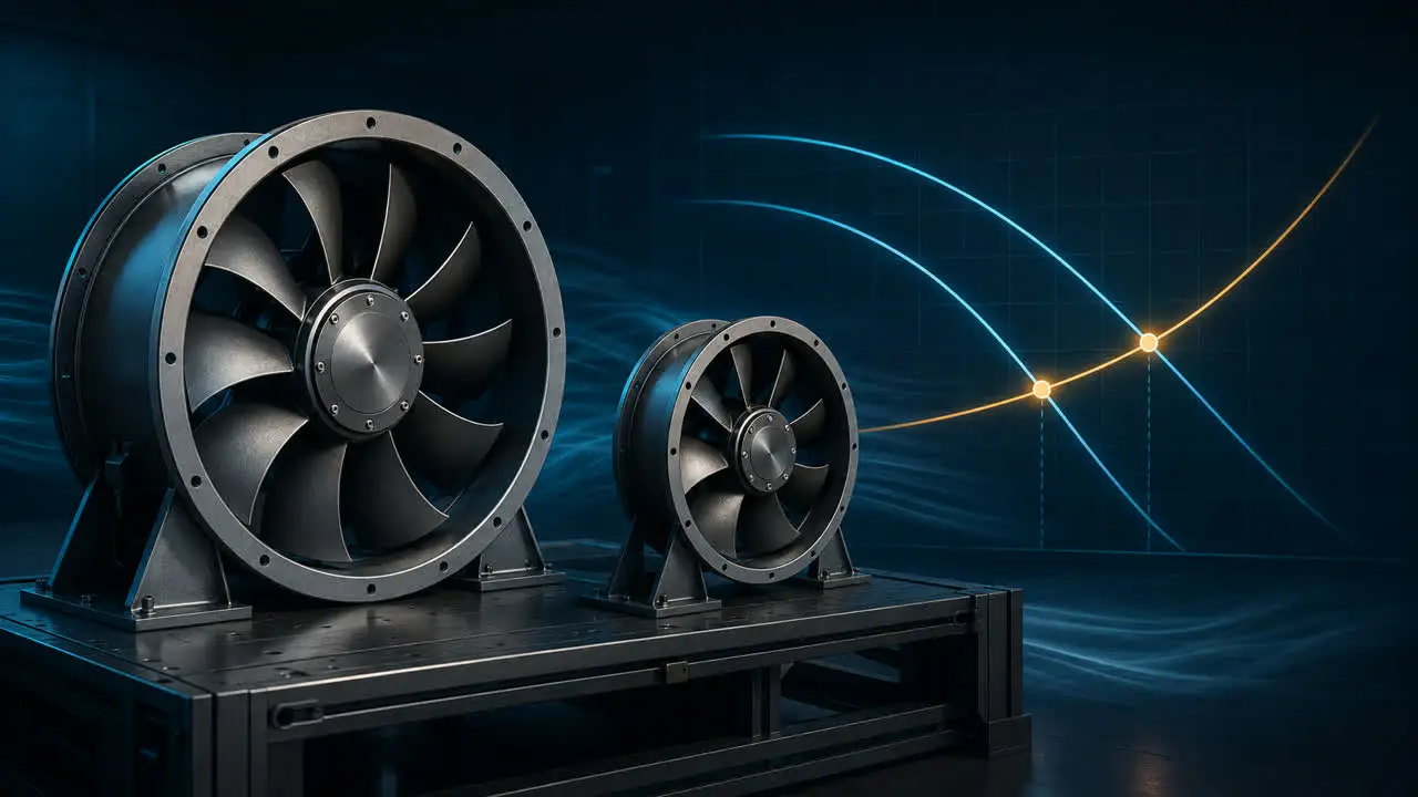
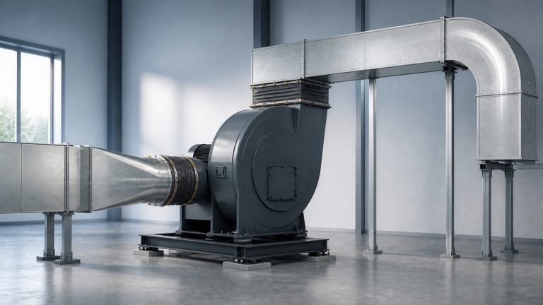
A physically bigger fan can look like the obvious route to more airflow. It may have a larger impeller, a wider wheel, a bigger housing or a higher motor rating. None of those dimensions, on its own, tells you how much useful air the installed system will receive.
The practical answer comes from the duty point: the airflow the application needs at the pressure created by the complete air path. A smaller fan can lead at one duty while a larger fan leads at another. The comparison only becomes meaningful when both candidates are evaluated on the same basis.
First define what “bigger” means
Fan size is not one variable. Diameter, wheel width, hub ratio, housing opening, motor capacity and overall footprint can all change independently. Products with the same nominal diameter may use different geometry, clearances, speeds and air paths.
Before comparing candidates, replace the vague request for a “bigger fan” with a precise requirement: required airflow, required pressure, available space, inlet and outlet arrangement, electrical supply, control method and the operating conditions that matter. This turns a size discussion into an engineering decision.
The operating point decides installed airflow
A fan curve describes the pressure a particular fan can develop as airflow changes under a stated test boundary. The system curve represents resistance from ducts, coils, filters, guards, grilles, bends, dampers, cabinets and other parts of the air path. Their intersection is the expected operating point.
That intersection can move even when the fan itself does not change. A more restrictive path raises the pressure requirement at a given flow, while a less restrictive path changes the relationship in the other direction. This is why a catalog endpoint cannot stand in for installed performance. Our guide to reading fan performance curves explains how to keep airflow, pressure and the test boundary attached to the same point.
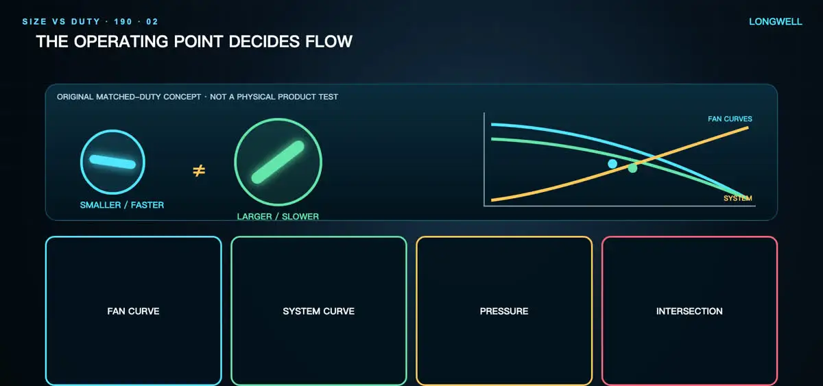
This original video frame illustrates a matched-duty comparison. It is not a physical product test, a model-specific curve or a measured performance claim.
Free-air values and pressure-rated values are not comparable
A maximum airflow value is often taken near the low-resistance end of a curve. An installed application may require the fan to work against a filter, heat exchanger, duct network or enclosure. Comparing one fan at free air with another fan at a stated pressure mixes two different conditions.
Put both candidates on the same basis. Confirm whether pressure is static or total, check the units, and keep speed, air density, inlet and outlet arrangement, and electrical boundary visible. A larger maximum number does not settle a duty elsewhere on the curve.
Fan architecture and geometry can outweigh diameter
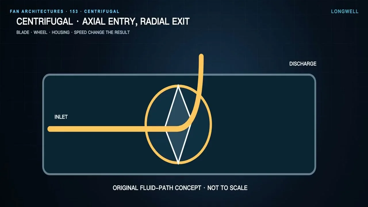
Air does not move through every fan in the same way. Axial, mixed-flow and centrifugal architectures use different flow paths, blade shapes and housings. Even within one architecture, pitch, chord, hub, tip clearance and scroll or shroud geometry influence the curve. Diameter is therefore only one part of the aerodynamic package.
The right architecture depends on the pressure-flow task and the physical installation, not a universal ranking. If the category itself is still undecided, this overview of centrifugal and axial fan differences is a useful starting point. Final selection still requires the applicable curve and installation data for the exact candidate.
Fan laws help only inside a similarity boundary
Fan-law relationships can help screen how a geometrically similar fan may respond to a change in speed or scale. They are not permission to transfer a result between unrelated designs. The assumptions become weaker when geometry, blade form, housing, clearance, air properties, control limits or operating regime changes.
Treat a scaled estimate as a hypothesis. Check it against current controlled performance data, recalculate the system-curve intersection and confirm motor and controller limits. Do not turn an ideal relationship into a guarantee for another fan or installation.
A bigger fan is not automatically quieter or more efficient
Lower rotational speed can sometimes support a quieter design, but sound depends on blade loading, turbulence, tonal content, inlet disturbance, mounting, structure and the measurement boundary. Efficiency likewise belongs to a specific operating point and defined input boundary. Physical size alone proves neither outcome.
Compare sound and input data at the same required airflow and pressure, using the same definitions. Also check the full intended control range rather than a single attractive point. A candidate that looks favorable at one condition may move into a less suitable region when filters load, dampers move or operating demand changes.
System effect can erase an apparent size advantage
A catalog curve belongs to a stated test arrangement. Tight inlet elbows, blocked intakes, abrupt discharge transitions, poor plenums and nearby obstructions can disturb the flow entering or leaving the fan. The installed result may therefore differ from an ideal comparison even when the selected curve is appropriate.
Before upsizing, inspect the whole air path. Removing an avoidable restriction may address the real problem more directly than changing diameter. This guide to improving airflow in ductwork helps separate system-side restrictions from fan-side selection.
Use measurements for the quantity they actually represent
Local air speed at an outlet is not the same thing as total volume flow unless the measurement method and effective flow area are defined. Rotational speed, current and input power can be valuable supporting signals, but none is a universal airflow meter. Their meaning depends on the specific fan, controller and operating boundary.
A defensible commissioning check starts with an appropriate airflow or validated proxy method, pressure measurements at agreed locations and the expected operating range. Electrical input, speed, sound and vibration should support that assessment rather than replace it.
A practical fan-size comparison checklist
- State every required airflow-pressure duty point, including important clean and loaded conditions.
- Define whether pressure is static or total and keep units consistent.
- Record air density or the temperature and altitude basis where relevant.
- Describe the complete inlet and outlet path, including coils, filters, guards and transitions.
- Compare exact fan curves at the same speed and test boundary.
- Read power, sound and operating limits at the same duty point.
- Check space, mounting, electrical, control and guarding constraints before changing size.
- Commission the installed system and compare the result with the agreed duty.
The better fan is not the largest one. It is the candidate whose verified curve and operating envelope match the required duty while fitting the mechanical, electrical and installation constraints.