A road tunnel fan is one part of a ventilation system, not a complete smoke-control solution. The useful first question is where air and smoke must travel under normal traffic, congestion and a fire. That answer depends on the tunnel geometry, traffic pattern, exits, portals, shafts and the approved emergency strategy. Only then can a fan duty and installed assembly be checked.
Start with the air and smoke route
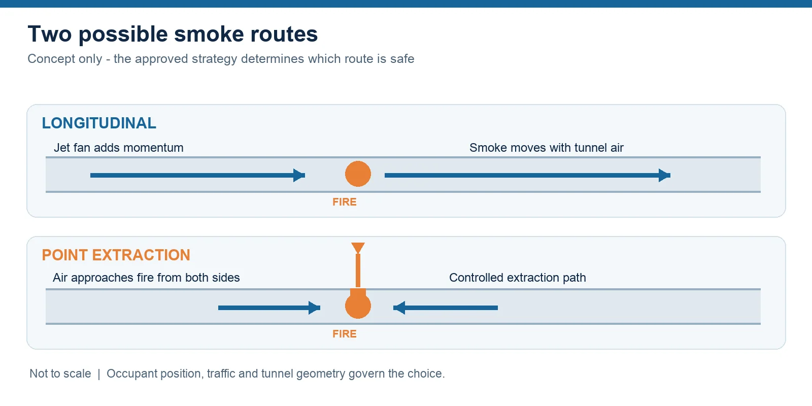
In a longitudinal arrangement, jet fans add momentum to air moving along the road tunnel. Their high-speed local discharge mixes with the wider tunnel stream; a fan’s free-air volume is not the same thing as the resulting tunnel flow. Portal wind, traffic, grade, wall interaction, obstruction and the next fan’s position can change the installed contribution. A semi-transverse or transverse arrangement uses a separate supply or extraction path, sometimes with controlled extraction close to an incident.
The topology is a project decision, not a universal tunnel-length rule. Traffic direction and the possibility of congestion affect which side of a fire may still contain people. PIARC’s road-tunnel design guidance distinguishes longitudinal flow from smoke extraction and describes why occupant location matters. The diagram below is a conceptual route map, not a tunnel layout or fire-engineering approval.
Separate normal operation from fire mode
Normal operation addresses air quality, visibility and the relevant environmental limits at portals or shafts. The engineer must document the applicable measurements, sensor positions, control stages and maintenance state. A demand-based control proposal needs a site-specific sequence and energy estimate; a generic fan-speed comparison does not establish savings for a tunnel with multiple fans and operating modes.
Fire mode needs a separate, approved cause-and-effect strategy covering detection, traffic stopping, egress, smoke direction or extraction, emergency power, communications and manual priority. In a longitudinal strategy, a target velocity may be used to limit upstream smoke backlayering, but its required value depends on the selected fire, tunnel section, grade, blockage and modelling assumptions. For congested or bidirectional traffic, directing smoke to one side may leave people downstream, so the design must consider the whole evacuation and extraction concept. See PIARC’s ventilation principles for those system distinctions.
Ask what the exact fan evidence proves
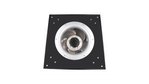
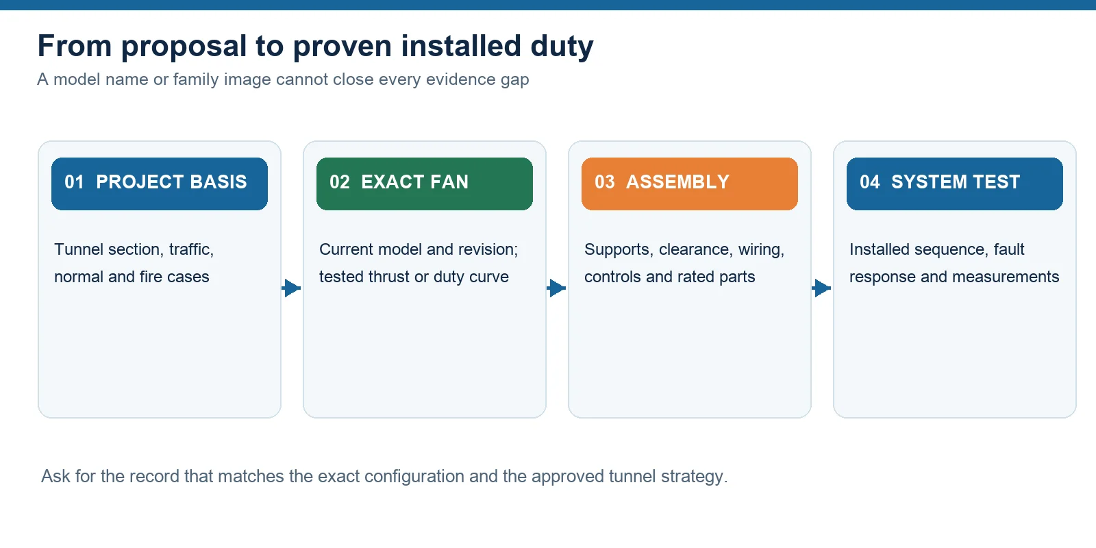
A jet fan candidate needs an exact model and revision, tested thrust in the specified direction, acoustic and electrical data, mounting and clearance details, and the intended ambient and emergency duties. For main axial or extraction fans, compare the tested pressure-flow data with the full network duty, including ducts, dampers, leakage and other losses. A catalogue image or outline is useful for identifying geometry; it does not establish installed thrust or smoke-control suitability.
Longwell’s tunnel airflow explainer shows the momentum-exchange principle and explicitly separates component selection from a complete tunnel assembly. Its industrial axial fan family is product-family context only. Neither page proves that a listed model meets this project’s thrust, heat-resistance or certification requirements. Request the current controlled drawing and test record for the exact configuration before adding a model to a project schedule.
Check the complete installation and control path
The fan is only one item in the operational chain. A proposal should show how the assembly is supported, how thrust and vibration loads reach the structure, where maintenance access sits, and how the electrical supply and controls behave after a fault. If emergency hot-smoke duty is required, the evidence must match the specified temperature-time exposure and include the configuration that will actually be installed: motor position, silencers, dampers, cables, supports and direction of operation as relevant. Do not infer a blanket fire rating from an unrelated fan-family brochure.
For jet fans, wall and ceiling clearance and spacing need installed-layout review. A downstream fan can capture an upstream jet before its momentum has mixed with the tunnel air. Longwell’s airflow explainer identifies those interactions as design inputs; it does not give a universal spacing rule. The tunnel engineer should document the geometry and analysis used for a proposed array.
Make modelling and commissioning traceable
Computational modelling can compare proposed normal and fire scenarios, but coloured contours alone do not verify an installation. Ask for the geometry, traffic blockage, fire definition, fan representation, boundary conditions, mesh or calculation method, sensitivity cases and acceptance criteria. Confirm who approved the assumptions and whether the chosen strategy addresses occupants on both sides of a potential incident.
Commissioning should then test the installed system against that documented strategy. Verify model and rotation or flow direction, sensor and detector inputs, staged normal operation, alarm response, emergency power, control overrides and selected failure cases. Record measured results and the method used to compare them with the design basis. The handover should make it possible to trace a claimed capability from model record to installed assembly to system test.
What to send for a useful supplier review
Send the tunnel section and route, traffic direction and congestion assumptions, the normal and fire operating cases, the authority-approved performance criteria, the proposed fan locations and the electrical/control schedule. Include an exact candidate model and revision if one exists. If those inputs are still being developed, start with the route and strategy rather than asking a supplier to select a fan from tunnel length alone. A supplier can then identify which controlled test and drawing records are available and where project engineering must close the remaining gaps.