What changed after our first proposal
An OEM building a new electronics cooling system asked us to modify a 172mm axial fan: 24 VDC, 48W, 4500 RPM, 500 units. Adding speed control turned out to be the real job.
We proposed a standard two-wire model meeting every figure in that brief. They rejected it, because adding speed control was the real requirement.
What the brief had left out
Their system needs dynamic speed control for thermal management. A fan that simply runs when powered cannot provide it, however well it matches the performance numbers.
To make the requirement unambiguous they sent the datasheet for the competing fan they were designing away from. That document showed a third wire accepting a 0-10V analog signal.
So the requirement was never really 4500 RPM. It was a functionally equivalent drop-in that integrates with a control scheme they already have, inside the same 172 by 51mm envelope.
What adding speed control actually takes
The gap between a two-wire and a three-wire fan looks small on a wiring diagram and is not.
Why you cannot just add a wire
A two-wire fan has a controller that runs the motor at one speed whenever power arrives. There is nothing inside it that reads an external signal.
Adding speed control means the motor controller board itself has to change. The third wire is the visible part of a different piece of electronics.
The path we did not take
Designing a new controller PCB from scratch was considered and rejected.
A new board means a design cycle, prototypes and a validation program. That conflicts directly with an OEM working to a launch date, and it spends engineering effort on something we had already solved.
Using what already existed
Instead the team took a motor controller from our SmartEC platform, which already handles both 0-10V analog and PWM signals.
Consequently a research problem became an integration task. The aerodynamic package, the frame, the bearings and the envelope all stayed as they were, and only the electronics changed.
What it cost
This is no longer a catalog part. It carries its own designation and its own minimum order, because the controller pairing is specific to it.
For 500 units a year that is comfortable. For someone needing five fans with speed control, the honest answer is to look for a standard three-wire model first rather than customizing a two-wire one.
Technical Specifications
Note the control input row below. That third wire is what this whole project was about.
| Parameter | Value |
|---|---|
| Model Number | LWAD17251MX-22-14 |
| Rated Voltage | 24.0 VDC |
| Operating Voltage | 12.0 – 27.6 VDC |
| Control Input | 0-10V Analog (via 3rd wire) |
| Input Power | 45.6 W (48 W Max) |
| Input Current | 1.9 A |
| Speed | 4500 RPM (±80) |
| Maximum Air Flow | 298.3 CFM / 506.8 m³/h |
| Maximum Static Pressure | 15.52 mm H₂O / 152.2 Pa |
| Acoustical Noise | 72 dBA |
| Dimensions (mm) | 172 x 162 x 51 |
| Weight | 740 g |
| Bearing Type | Dual Ball Bearing |
| Frame / Impeller Material | Aluminum-Plastic UL94V-0 / PBT Plastic UL94V-0 |
| Insulation Type | UL Class A |
| Life Expectancy | 50,000 Hours @ 25°C |
Technical Documentation
Final Technical Specification (LWAD17251MX-22-14)
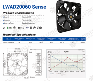
Here the final technical specification for model LWAD17251MX-22-14 details performance curves, dimensions, and the 3-wire 0-10V control pinout for system integration.

The Longwell LWAD17251 series provides the mechanical frame for this custom electronics cooling fan.
Initial 2-Wire Proposal (LWAD17251MX-22-00)
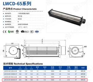
Meanwhile the initial 2-wire proposal, model LWAD17251MX-22-00, provided the baseline performance metrics for the project.
Customer-Provided Functional Benchmark
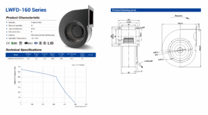
The customer provided this competitor datasheet as a functional benchmark, highlighting the critical need for 0-10V speed control.

A pricing analysis was conducted, demonstrating a significant cost advantage for the 500-unit order volume.
If you need control on an existing fan
Adding speed control gets discovered late more often than any other requirement.
- State the control scheme before the performance figures. Adding speed control changes which fans are candidates, and it is not something that can be bolted on afterwards. Naming it first avoids a proposal round that ends in rejection.
- Send the datasheet of the fan you are replacing. This customer did, and it settled the ambiguity in one step. A datasheet shows the control interface, the pinout and the signal type without anyone having to describe them.
- Ask whether the controller already exists. A supplier with a control platform can integrate in weeks. One designing a board for you is starting a project, and the difference shows up in both schedule and risk.
- Check what the third wire expects. 0-10V analog and PWM are not interchangeable, and some fans want a tachometer output on a fourth wire. Confirm the signal type against what your controller actually produces.
See our axial fan range, the DC axial fan section, or speed controllers. Safety testing follows UL 507.
Questions about control inputs
Can a two-wire fan be converted to three-wire?
Not by rewiring. The controller board inside decides whether the fan can read an external signal, so conversion means changing that board. Where the fan is otherwise right, that is a worthwhile modification. Where a standard three-wire model exists, take it instead.
What is the difference between 0-10V and PWM control?
Only how the speed command is sent. A 0-10V input needs an analog voltage, which often means a DAC or filter on your controller. PWM sends a square wave whose duty cycle carries the value, which suits a microcontroller output directly. Pick whichever your board already produces.
Does the fan report its speed back?
Only if it has a tachometer output, usually on a further wire. That signal is worth taking in any sealed enclosure, since it turns a silently failed fan into an alarm. Confirm it is present rather than assuming, as it is a separate feature from speed control.
Why does the operating voltage range go down to 12V?
To tolerate a supply that sags under load or during inrush. The fan holds its commanded behavior across that window rather than following the rail. It also means one part can serve a nominal 24V system and a lower-voltage one where reduced airflow is acceptable.
Technical Documentation & Resources
Working on something similar?
Send us the duty point, the envelope and the supply, and our engineers come back with a shortlist rather than a catalog. Meanwhile custom spec sheets and samples run to 90 days. Since 1990 we have built fans for HVAC, cold chain, data center and industrial OEMs.
Browse Related Products:
🏆 ISO 9001 / ISO 14001 / ISO 45001 | CE (TÜV) | UL/ETL | ATEX Zone 21/22 | AMCA 210/211 / ISO 5801 tested