Key Takeaways
- In most air-cooled data centers, the fixed-speed fans draw near-rated power across the 40–70% load band and are billed that way continuously.
- 7 fan-level causes stack up: fixed-speed operation at part load, inefficient motors and drives, operation off the best-efficiency range, excessive airflow-path resistance, cold-air leakage and bypass, hot-air recirculation, and controls mismatched to demand.
- Selection margins multiply rather than add, which turns a 100% airflow requirement into a 150% machine that never runs at its best-efficiency point.
- Reset the controls and seal the airflow path before retrofitting the system.
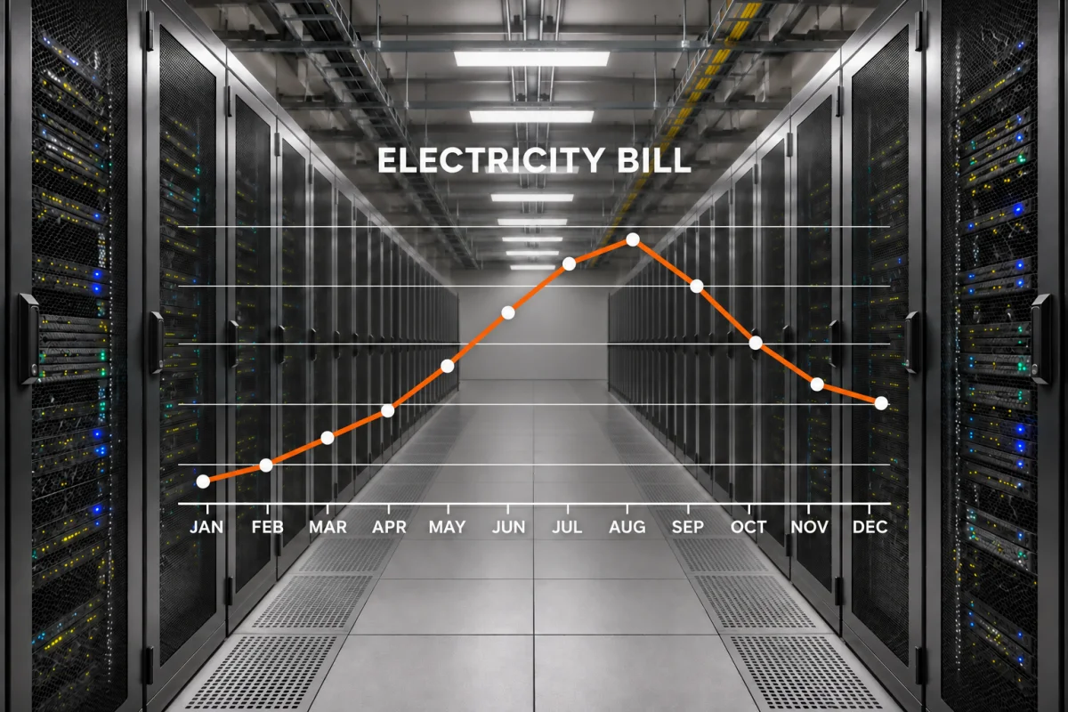
When a data center receives a high bill, the first suspect is almost always the chiller. However, that suspicion points at the wrong machine in most air-cooled data halls. A large share of cooling energy is spent inside the CRAH units, where fans run all day and night. The fan load and their running speed are never matched, and none of the waste raises an alarm. This article breaks data center cooling fan energy waste into seven causes, and provides the solution for lowing bill.
Where does the Cooling Bill Actually Go?
- Chiller / chilled-water plant: compressor and condenser work. It is the largest single load on the cooling side, and its cost moves with outdoor temperature. The warmer the air at the condenser, the more work each unit of heat rejection takes, so the same room costs more to cool in a hot month than in a mild one.
- Distribution: pumps and air movers. This block is the main cost of the cooling bill. Every liter of water or cubic meter of air moved is counted on the bill.
- Terminal: the CRAH/CRAC fan and its controls. Fans are the only cooling load that runs at near-constant power all year. A fixed-speed fan draws close to its rated power and speed whether the room sits at 40 percent of design load or at full design load. The kWh is billed at essentially the same rate every one of the 8,760 hours, 365 days, whatever the room actually needs.
7 Fan-Level Causes of High Data Center Cooling Bill
Cause 1: Excessive Fan Speed at Partial Load
This is the dominant electrical loss. A CRAH is sized and run at its peak load, but the actual IT load typically sits at 40% to 70% for most operating hours. Excess airflow gets absorbed by a damper, a bypass, or simply by over-cooling the room, and the fan keeps drawing near-full power.
Fan laws describe their proportional relationship:
- Airflow ∝ speed
- Pressure ∝ speed²
- Shaft power ∝ speed³
E.g. At 70% speed, the ideal shaft power is roughly 34% of full speed.
There are two corrections that must be applied. The first point is that electrical input does not follow the cube change exactly. Motor part-load efficiency falls, and the VFD has its own losses. The second point relates to the weighted energy calculation method. A unit at 45% load in January and 90% in July does not save the same as one that uses 50% all year.
Cause 2: Energy Losses in Inefficient Motors
The energy losses are independent of motor type. A common misconception is comparing AC motors with EC motors in efficiency. It is cleaner to separate two independent loss sources. An AC induction motor peaks in efficiency near rated load and rated speed. At part load and reduced speed, efficiency falls. Add a VFD, and its losses are added on top. When the operating point moves away from the impeller’s best-efficiency region, flow losses in the impeller and housing rise. An EC motor does not fix this.
The advantage of an EC motor is real but conditional: it holds efficiency across a wide speed range and allows continuous modulation. Neither property helps if the fan is still running far off its best point.
Cause 3: Fan Operation Outside the Best-Efficiency Range
The original selection is the key point that oversized the fan. When multiple margins are applied to the same airflow requirement, they multiply:
1.15 (load margin) × 1.10 (duct margin) × 1.20 (future growth) ≈ 1.52
It results in a nominal 100% airflow requirement becoming a 150% airflow machine. That fan then runs far to the right of its intended duty point, at lower efficiency.
The root cause of this oversized selection is the order error. An engineer should choose a model first and back-calculate the operating point. Check whether the operating point is near the best operating point. There are also fan selector tools to help double-check the selection process.
Cause 4: Excessive Resistance in the Airflow Path
Part of the system resistance is not calculated in the system resistance. Undersized ductwork and pressure losses raise the system curve permanently, and the fan carries that burden every hour of the year. System effect at the fan inlet and outlet, meaning uneven flow at the connection. These factors add system resistance.
Other resistances accumulate as the service life increases. As filters collect dust and coils become fouled, airflow resistance gradually increases. The change may be too small to notice from week to week, but it will be significant over one year. Any post-filter added downstream of the fan, whatever its justification, is a permanent addition to that resistance.
The speed controllers can make the problem harder to spot. In a constant-speed fan, airflow may fall as resistance rises. Lowering the supply-air temperature to compensate can mask the airflow problem while increasing cooling demand. In a variable-speed unit, the controls may increase fan speed to maintain the airflow or pressure target, depending on the sensor location and control strategy.
Cause 5: Cooled Air Leakage
Cooled air that returns to the cooling unit without passing through servers wastes fan energy. Unsealed cable openings, gaps in raised floors, missing blanking panels, and open containment doors can allow air to escape its intended path. Leakage is usually treated as a single fault. Four areas deserve inspection: room and rack openings, closed dampers, air-distribution hardware, and containment boundaries.
Bypass inside the room: open tiles in the cold aisle, missing blanking panels in partly populated racks, unfilled grommets, open cable penetrations. The cooled air leaves the fans, crosses the aisle, and returns to the fan without reaching the hot components.
A damper works as a flow controller but not a seal. The leak grows as the damper is not working. The cooled air can also escape through seams, connections, and penetrations. The air path of containment will also increase the leakage.
All these do the same thing. The air is cooled, filtered, and moved, then discarded. Return temperature drops, coil delta-T shrinks, the unit seeks more airflow, and the extra airflow finds more gaps.
Cause 6: Hot-Air Re-circulation at Server Intakes
Exhaust air that re-enters a server intake raises the temperature. The paths are physical: gaps above and between racks, high-exit-velocity servers exhausting into an uncontained aisle, and return air short-cycling from a unit back toward its own supply. None of these paths show up as a fault. The room looks orderly but runs warm.
Recirculation pushes fan power up twice. The affected servers see warmer air, and their own fans ramp up to hold component temperatures, which is cooling energy spent by the IT floor. The cooling fans respond repeatedly to the hot temperature. In order to hold rack inlet at the set point, they are driven to cooler supply air or higher airflow. The room can appear short of cooling while its actual operating capacity is not reached.
Cause 7: Fan Controls Mismatched to Cooling Demand
Fan controls waste energy when they maintain more airflow or pressure than cooling requires. Two common causes are using dampers to restrict excess airflow and keeping pressure set points unchanged as operating conditions evolve.
In a raised-floor data center, a fixed plenum-pressure set point can create a similar mismatch. A setting established during commissioning may no longer suit the current IT load, rack arrangement, or floor-tile layout. Maintaining unnecessarily high pressure can deliver excess airflow and increase leakage through unsealed openings.
The system set point is usually designed based on the hottest day of the year, and it is rarely revised. If there is no controller, the system is working continuously under the highest pressure and airflow requirements. This also results in a high bill.
How to Lower the Data Center Cooling Bill?
Reset the Controls
Review fan-speed and pressure settings against current IT loads and rack-inlet temperatures. Set points established during commissioning may no longer suit the room’s operating conditions. Reduce unnecessary plenum pressure and adjust fan speed, where variable-speed control is available.
Supply-air temperatures can also be adjusted while keeping server-inlet conditions within the applicable equipment limits and ASHRAE guidance. Verify the changes across different loads before using the measured airflow and pressure to size a fan upgrade.
Seal the Airflow Path
Every gap on the airflow path turns moved air into waste before it reaches an intake. Install blanking panels in unused rack spaces, seal cable penetrations and floor openings, and repair gaps in containment panels and doors.
With those paths closed, cold-air bypass and hot-air recirculation both shrink. Loaded filters and fouled coils add resistance on top of the leaks, so clean them as a separate task to take pressure off the fan.
Upgrade to LONGWELL EC Fan Wall
Upgrading the fans can further reduce cooling energy use. LONGWELL EC FanGrid replaces a traditional belt-driven blower in an existing CRAH or AHU with an array of direct-drive EC plug fans.
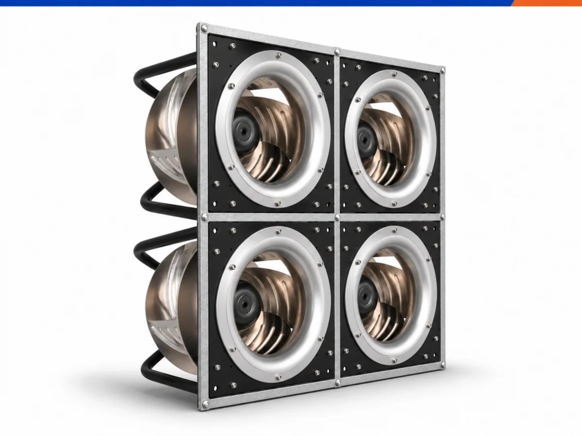
Adopt an N+1 (or N+2) redundancy design to ensure system reliability. Each fan operates independently but works collaboratively, with an integrated intelligent control system. The data center project indicates approximately 35% energy savings and a 25% lower fault rate.
The AC/DC/EC three motor platforms operate in parallel, equipped with independent production lines, independent engineering teams, and sharing testing facilities. LONGWELL can recommend the appropriate platform based on the application.
FAQ
Which cooling-system types are available for data centers?
The common options include air cooling and water cooling. Room-level low-to-moderate rack densities circulate cool air across server hardware. For data centers designed for high-density AI and high-performance computing workloads, liquid cooling is more efficient.
What is the best way to cool down data centers?
There is no single best method, but the best-performing rooms do the same three things. They contain hot and cold aisles so supply and exhaust do not mix, they move only the airflow the IT load needs, and they run fans at variable speed against measured demand instead of fixed set points.
Can existing CRAH units be upgraded with more efficient fans?
Yes. The belt-driven or fixed-speed AC assembly is replaced with direct-drive EC plug fans matched to the measured duty point, while the frame, coil, and unit controls stay.
Which cooling approach offers the greatest energy efficiency?
No single approach is most efficient in every facility. For the fan block, parallel EC fans at variable speed, under containment, and with static pressure reset. This is currently the more efficient solution, but it also has the drawback of requiring a relatively high initial investment.