Two lengths, one tight cross-section
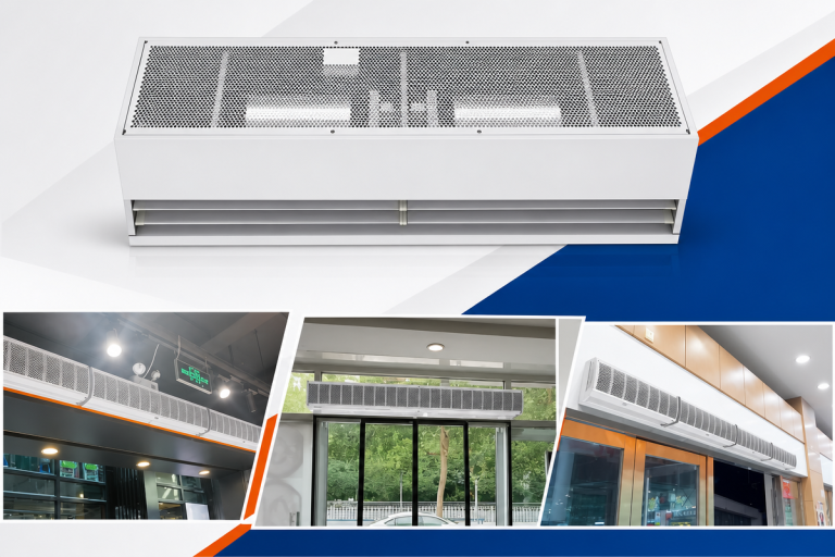
A commercial HVAC OEM needed EC cross-flow fans for low-profile air curtains and trench heating modules, and the housing gave the fan 120 by 120mm of cross-section to live in. The external rotor motor is what made the rest of the specification possible inside that box.
Two variants were required, scaled to two cabinet widths.
What each variant had to do
- First, the 350mm blower: 450 m3/h against 40 Pa, inside 51 dB(A).
- Next, the 520mm blower: 650 m3/h against 59 Pa, inside 53 dB(A).
- Meanwhile both run on 230 VAC single phase, from -25C to +60C.
- Finally, both take 0-10V or PWM speed control, because a building management system drives them.
Why AC was rejected in one paragraph
A shaded-pole AC blower cannot take an analog control signal, and an inverter bolted beside it would not fit the box. Nor would its cost fit the product. So the motor had to be EC, and it had to be small.
How an external rotor motor works
A normal motor spins a shaft inside a fixed casing. An external rotor motor turns that inside out: the windings sit still in the middle, and the outer shell of the motor is the part that spins.
Why inside-out saves space
The impeller mounts straight onto the spinning shell. So there is no shaft coupling, no separate hub, and no motor body hanging outside the airflow path.
In a 120mm cross-section that geometry is the difference between fitting and not fitting. The motor effectively disappears into the end of the impeller.
What else the architecture buys
Here the spinning shell doubles as a flywheel, which smooths the speed under the pulsed drive of an EC controller. In short, the mass sits where it helps.
Meanwhile the integrated electronics take the 0-10V or PWM signal directly, so the building management system talks to the fan with two wires and no external drive.
What it costs
Honestly, an external rotor motor sheds heat less easily than a normal one, because the windings sit at the middle of the assembly rather than against an outer casing.
That matters at the +60C end of this job. So we checked the winding insulation and the electronics rating at that corner, not at room temperature, before freezing the design.
One platform, two fans
Both variants use the same motor and the same 80mm impeller profile. They differ only in length. So one control interface, one spare part and one approval covers the pair.
The published curves follow ISO 5801 test methods, measured per variant rather than scaled from one.
Technical Specifications
Two variants share every figure below except length, airflow and noise. That is the point of building on one motor platform.
| Parameter | LWCE-80350SN-06 | LWCE-80520SN-06 |
|---|---|---|
| Voltage (VAC) | 230 | 230 |
| Voltage Range (VAC) | 184-276 | 184-276 |
| Frequency (Hz) | 50/60 | 50/60 |
| Speed (RPM) | 1500 | 1500 |
| Input Power (W) | 16 | 23 |
| Airflow (m³/h) | 450 | 650 |
| Airflow (CFM) | 265 | 382 |
| Max Static Pressure (Pa) | 40 | 59 |
| Noise dB(A) | 51 | 53 |
| Max Temp (°C) | 60 | 60 |
| Min Temp (°C) | -25 | -25 |
| Rotation | CCW | CCW |
| Total Length A (mm) | 473 | 643 |
| Mounting Length B (mm) | 365 | 535 |
| Blower Length C (mm) | 350 | 520 |
| Housing Profile (mm) | 120 x 120 | 120 x 120 |
| Impeller Diameter (mm) | 80 | 80 |
| Impeller Material | Aluminum Alloy | Aluminum Alloy |
| Frame Material | Cold Rolled Steel | Cold Rolled Steel |
| Insulation Class | B | B |
| Bearing Type | Ball Bearing | Ball Bearing |
| Lifespan (L10) | 30,000 hrs at 25°C | 30,000 hrs at 25°C |
| Certifications | CE | CE |
Technical Documentation
Below are the approved project outputs generated during the PM Assignment and Technical Review phases. These documents represent the finalized standards for the LWCE-80 series and are stored in the Longwell archive.
Download LWCE-80350SN-06 Specification Sheet (PDF)
This document contains the finalized performance parameters, P-Q curves, and dimensional drawings for the 350 mm impeller variant, required by the customer’s mechanical design team to verify physical clearances.
Download LWCE-80350SN-06 Original Engineering Source File
This source file houses the raw technical data and safety warnings compiled during the engineering phase, serving as the basis for the printed labels and installation manuals.
Open LWCE-80520SN-06 Specification Sheet (PDF)
This technical file provides the specific 650 m³/h airflow data and 59 Pa pressure metrics for the 520 mm impeller variant, essential for HVAC engineers calculating total room air changes.
Download LWCE-80520SN-06 Original Engineering Source File
This internal document contains the editable text and layout formatting used by the Longwell documentation control team prior to final PDF publication and archive filing.
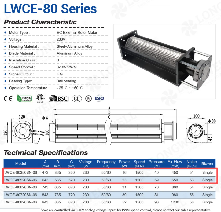
This catalog image presents a side-by-side comparison of the entire LWCE-80 product family, allowing procurement managers to quickly reference voltage, RPM, and dimension scaling across the series.
When this architecture earns its place
An external rotor motor is not automatically the right answer. These four checks tell you when it is.
- Reach for it when the envelope is tight. An external rotor motor buries itself in the impeller, which is worth tens of millimetres in a duct or cabinet. If space is generous, a conventional motor is easier to service and cools itself better.
- Check the thermal corner, not the nominal rating. The buried windings run warmer. Ask for the winding temperature and electronics rating at your maximum ambient, because that is where this architecture gives back some of what it saves in space.
- Confirm the control signal end to end. Integrated EC electronics accept 0-10V or PWM directly, but the building management output and the fan input still need matching. Settle signal type, voltage range and failure behavior before the first sample.
- Use the shared platform deliberately. If two lengths or duties can ride one motor, qualification, spares and documentation all halve. Ask the supplier which of their variants share a platform before inventing a new one.
See our cross-flow fans range, the EC cross-flow fans section, or cross-flow impellers.
Questions about external rotor motors
Why do so many EC fans use external rotor motors?
Because the two technologies fit together. EC control needs electronics close to the windings, and the external rotor layout leaves the stationary center free for exactly that. The result is a motor, drive and hub in one compact assembly.
Does the spinning outer shell wear faster?
No; the shell carries no rubbing contact. The bearings between the stationary center and the shell do the same work shaft bearings would. What deserves attention instead is heat, since the windings sit away from the cooling airstream.
Can an external rotor motor be repaired in the field?
Rarely, and the design does not intend it. Motor, hub and often the impeller form one balanced assembly, so field service means exchanging the unit. Plan spares accordingly rather than budgeting for winding repairs.
What happens to these fans if the control signal is lost?
That is configurable, and it is worth specifying rather than discovering. Depending on setup, the fan can stop, run at a fixed speed, or hold its last commanded speed. For a heating module, decide which failure behavior is safe and put it in the order.
Technical Documentation & Resources
Need the same thing for your own unit?
Give us the numbers and the envelope, and you get a shortlist rather than a catalog. Meanwhile custom spec sheets and samples run to 90 days. Since 1990 Longwell has supplied EC fans and blowers to OEMs in HVAC, cold chain, data center and industrial markets.
Browse Related Products:
🏆 ISO 9001 / ISO 14001 / ISO 45001 | CE (TÜV) | UL/ETL | ATEX Zone 21/22 | AMCA 210/211 / ISO 5801 tested
Choose the right external rotor motor
Longwell manufactures 11 external rotor motors in-house. Send airflow, static pressure and voltage — an engineer replies with a matching model, performance curve and price within one working day.