Matching every fan’s speed command is not the same as balancing a fan wall. Identical speed readings or similar motor currents do not establish equal airflow, either. A useful balancing exercise starts with the required air distribution, checks how it will be measured, and then adjusts the array within its approved operating limits.
This guide is for engineers planning or reviewing commissioning. It explains what to record and how to interpret changes, not a universal control setting or a substitute for the equipment manufacturer’s procedures.
Define which airflow result you need to balance
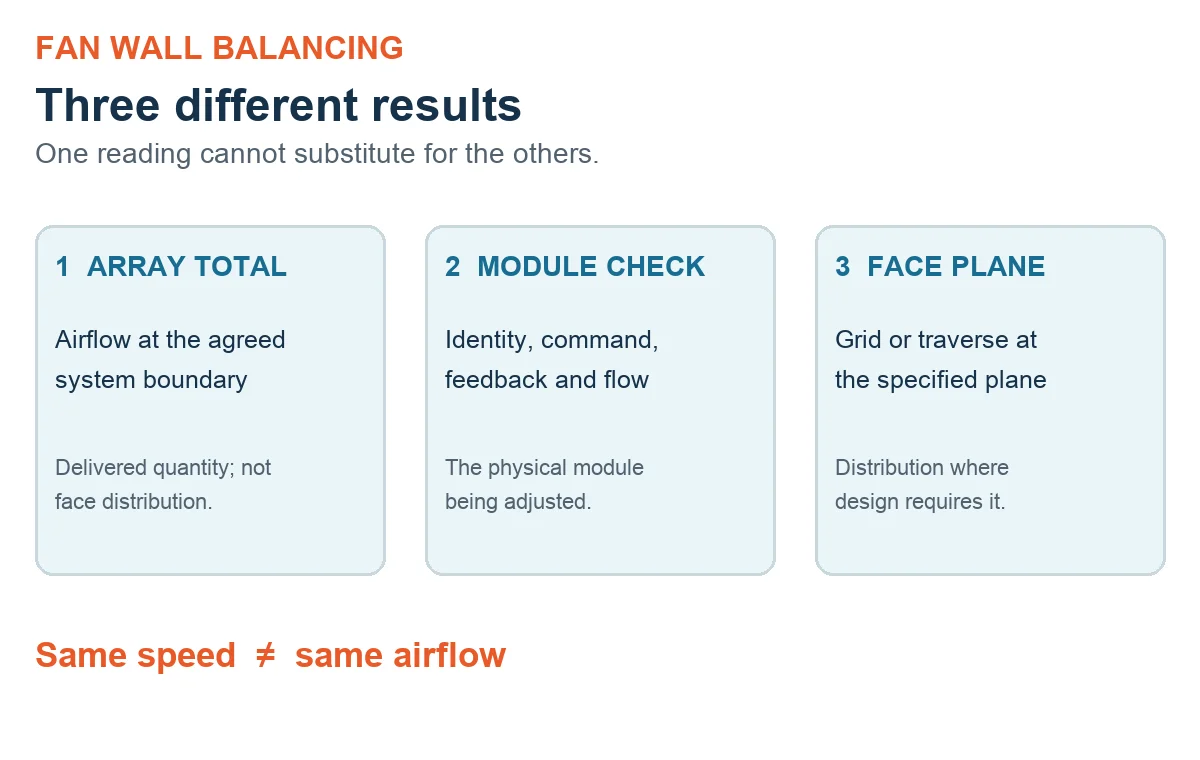
Separate total array airflow, common pressure, individual module airflow and downstream coil or filter face uniformity. They answer different questions. Meeting the total airflow target does not, by itself, demonstrate an acceptable distribution across the coil face. A common pressure reading is not a measurement of each module’s contribution.
Agree the measurement locations, operating states and acceptance criteria with the responsible designer before making adjustments. Do not assume the design calls for identical flow through every module. If the requirement is face uniformity, define the relevant downstream plane and assessment method rather than substituting a set of speed readings.
Make the baseline repeatable before changing speeds
A before-and-after comparison is useful only when its conditions are known. Record the measurement plane and grid, instrument calibration, air-density basis and uncertainty. Identify the pressure definition and sensor locations. Let the specified operating condition stabilize before collecting the baseline, and record filter condition and the active control mode.
Keep a compact measurement record alongside the controls log:
| Record | Include |
|---|---|
| Measurement method | Plane, grid, instruments, calibration and uncertainty |
| System condition | Air-density basis, filter state, pressure and control mode |
| Module readings | Module identity, command, feedback and measured airflow |
| Adjustment result | Changed setting, stabilized readings and rollback setting |
Do not chase a small apparent difference without considering the measurement uncertainty. If the method cannot distinguish the change reliably, resolve that limitation before treating another speed adjustment as an improvement.
Check module identity and the physical air path
Confirm which physical fan belongs to each control address and feedback channel. Check module identity, sensor assignment and control calibration before interpreting an uneven pattern. A mislabeled channel can send the adjustment to a different fan from the one being measured.
Then review the air path: plenum geometry, inlet and discharge pressure conditions, leakage, filters and obstructions. Manufacturing and installation tolerances may also affect distribution. Similar-looking modules do not prove that these conditions are identical. Establish what differs before deciding that software trimming is the appropriate correction.
Read the fan wall as a shared system
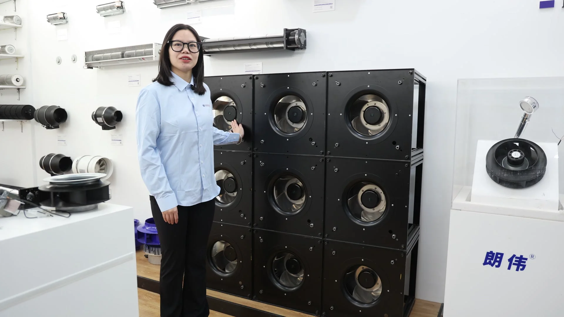
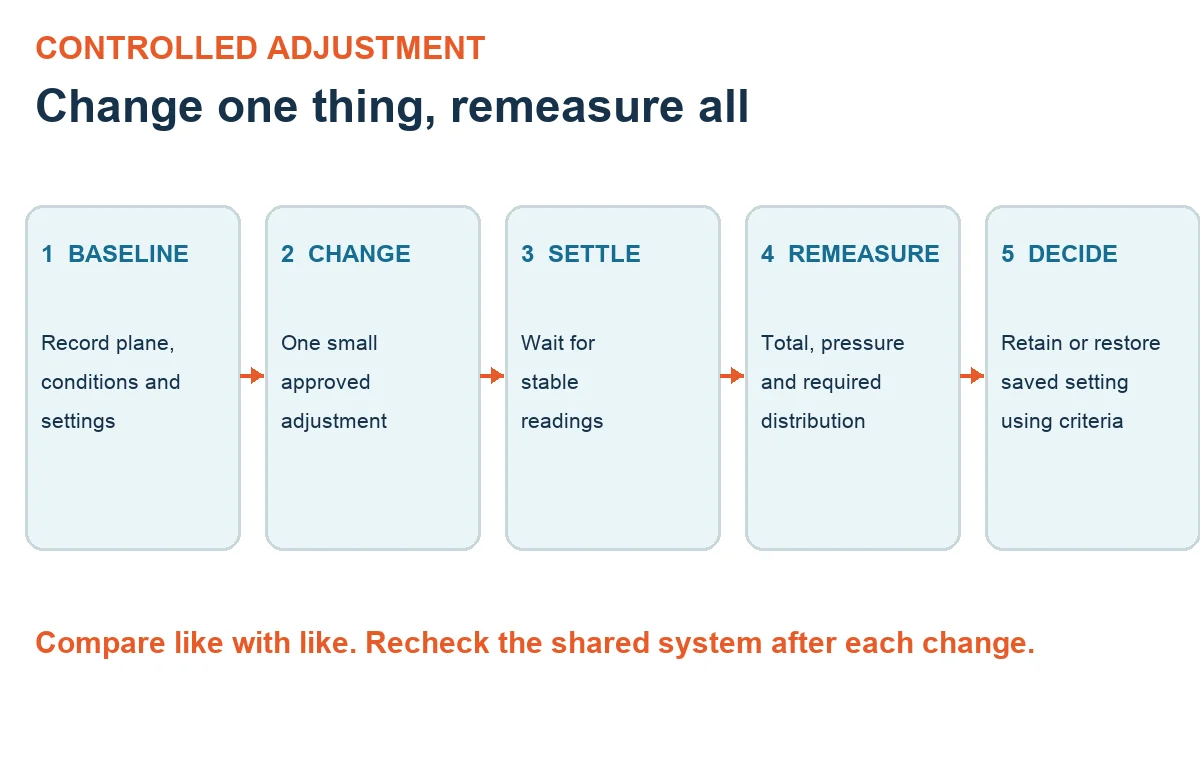
Parallel fans interact through the system they serve. Adjusting a module can change the operating conditions seen by the others, so checking only the adjusted fan leaves part of the result unmeasured. Recheck the array total, relevant pressure readings and the distribution that the project actually requires.
The centrifugal fan curve guide provides background for discussing duty points and pressure. Use the applicable manufacturer’s data for the selected modules and installation conditions; a generic curve is not a calibration for the assembled wall. Keep speed, power, temperature, vibration and stable-flow limits in view while evaluating any proposed adjustment.
Adjust in small steps and preserve a rollback point
Start from a recorded, stable baseline. Under the approved commissioning plan, make a small, deliberate change, allow the system to settle, and record both the setting and the resulting measurements. Keep the other test conditions consistent so the comparison has meaning.
Decide whether to retain or reverse the change using the agreed acceptance criteria and manufacturer-approved limits. Preserve the previous setting before moving on. If another control loop changes state, or a filter or obstruction is corrected, document it and establish a comparable baseline rather than attributing the entire difference to the speed trim.
The endpoint is a documented operating condition that meets the project’s requirements within the applicable limits. There is no universal balancing tolerance or fixed energy-saving result that can be assigned to every fan wall.
Check standby transitions under an approved test plan
If the project requires fault or standby testing, define the planned state, monitored readings and abort criteria beforehand. Assess the remaining array against its approved limits; do not assume automatic compensation or unchanged distribution when a module becomes unavailable.
A stop command is not electrical isolation. This guide does not describe live removal or replacement. Access, isolation and maintenance belong to qualified personnel following the specific equipment procedures. Keep those activities separate from observing a controlled commissioning test.
Record the final operating condition, not just the settings
Hand over the total airflow and pressure, distribution at the agreed plane, final commands and feedback, operating-limit checks and any approved standby-test results. Keep measurements tied to the state in which they were taken so a later service visit has a baseline to compare.
For a component discussion, the Longwell EC plug fan range is a series-browsing starting point, not confirmation of suitability for a particular wall. Prepare the layout, airflow and pressure requirements, module identities, measurement method and control sequence so the specific selection evidence can be reviewed.