A dryer booster fan that does not turn on is a system symptom, not proof of a failed motor or pressure switch. The call can be lost at the dryer, lint path, duct, sensing port, controller, power supply, fan, or outdoor termination. A deliberate check of that whole path is safer than repeatedly cycling the dryer or swapping the first part that looks familiar.
This guide is for external observation and manual-approved, owner-accessible checks. Opening a fan, controller, junction box, gas-appliance path, concealed duct, or circuit belongs to qualified service. Exact instructions, listings, the installed design, and local rules control the repair.
Stop first for heat, smoke, gas, or carbon-monoxide warnings
Stop using the dryer for smoke, scorching, a burning odor, abnormal heat, repeated thermal trips, damaged wiring, a disconnected duct, or lint leaking around joints. Do not keep restarting it to see whether the booster reacts. U.S. Fire Administration guidance makes lint-filter and vent cleaning core dryer-fire prevention, so restriction is a safety question first.
For a gas dryer, gas odor, soot, a carbon-monoxide alarm, suspected spillage, or unusual heat ends troubleshooting. Follow emergency guidance and obtain qualified fuel-gas and exhaust evaluation. A booster cannot make a leaking or blocked gas-dryer exhaust safe.
Confirm that this exact system permits a booster
Record the dryer model, booster model, control type, duct route, location, and manuals. Some systems use a listed dryer exhaust duct power ventilator with defined access, sensing, cleaning, and placement requirements; others may not allow the arrangement. Diameter alone does not establish compatibility.
Identify what commands the fan: a diaphragm pressure switch, airflow sensor, current relay, temperature input, or integrated electronics. Start and stop behavior varies. Never import a pressure setting, delay, wiring diagram, or replacement part from another product.
Trace the complete call path before blaming the switch
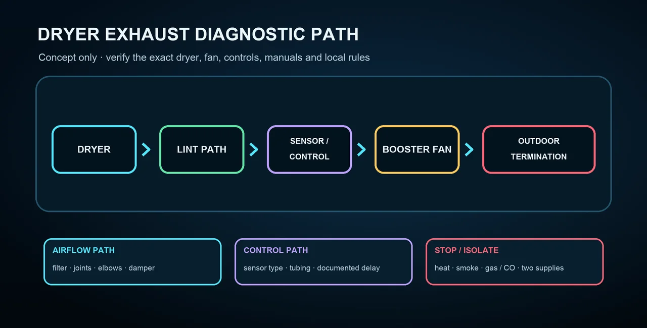
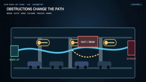
Follow the sequence from the appliance to the exterior: dryer call, accessible lint path, transition connector, rigid duct and elbows, sensing pickup and tubing, controller, booster housing, downstream duct, damper, and outdoor termination. The illustration is conceptual; it does not identify a product or prove that a booster is suitable. This duct-fan architecture overview can help distinguish an inline arrangement, but its generic claims and dimensions are not dryer-exhaust instructions.
A blockage can create abnormal pressure, while an upstream leak can hide the expected signal. A crushed transition, separated joint, stuck exterior flap, clogged lint path, or inaccessible cleanout can therefore look like a bad sensor. Correct an authorized airflow-path problem first.
Use external observations before opening any component
- At the dryer: note the cycle, whether heat is present, drying time, lint-filter condition, and any protection event. Do not reach into an operating appliance.
- Along accessible duct: look for crushing, disconnection, leakage, unusual lint, unsupported sections, or damage without disturbing concealed work.
- At the termination: from a safe position, observe whether the damper opens as the exact instructions describe. Do not add a screen or obstruction that can trap lint.
- At the booster: record sound, vibration, indicators, and documented timing with guards in place. Silence does not prove a dead motor.
Do not bypass contacts, apply direct mains power, live-back-probe terminals, enlarge a port, add an improvised tee, or blow or suck on tubing by mouth. Those shortcuts can cause uncontrolled operation, damage, contamination, and lost evidence.
Separate a documented delay from a no-start condition
Some controls intentionally wait, cycle under defined logic, or run after the dryer stops. Observe only for the interval in the exact current manual and with the system guarded. There is no safe universal wait time.
Compare the observed sequence with the documented sequence: what input should appear, what indicator should change, when the fan should start, and when it should stop. If the manual, label, and installed wiring disagree, stop. Do not adjust a sealed threshold or rotate a switch assembly unless the manufacturer explicitly authorizes that exact procedure for that exact model.
Control both electrical supplies before qualified testing
The dryer and booster commonly have separate supplies, and automatic controls may start the fan or retain a delay. OFF or silence does not prove isolation. Before exposed electrical work, qualified personnel identify all sources, disconnect them, prevent restart, control stored energy, and verify de-energization with suitable test equipment.
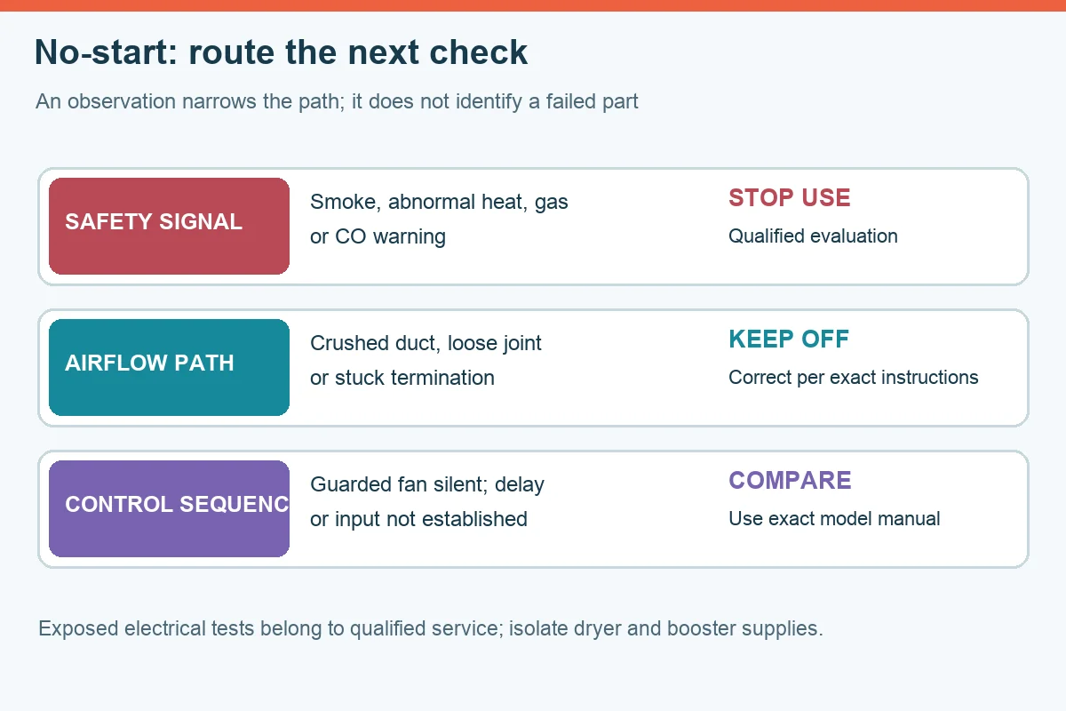
| Observed condition | Bounded next action |
|---|---|
| Restriction, damage, leakage, or a stuck termination is visible | Keep the system off and correct the exhaust-path condition under the controlling instructions. |
| Tubing is loose, split, contaminated, or routed differently from the manual | Do not improvise; request exact-model service and replacement guidance. |
| The documented input is present but the control sequence is absent | Qualified service checks the exact sensor, controller, and wiring without bypassing safety functions. |
| The controller calls but the guarded fan does not run | Qualified service evaluates supply, protection, motor, wheel, and mechanical freedom using the manufacturer procedure. |
| Identity, listing, wiring, or manuals are missing or conflicting | Stop and resolve the documentation and compatibility gap before further testing. |
Match replacements to the exact control and environment
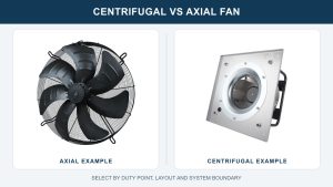
A similar housing or equal voltage is not enough. Match the approved application, contact logic, electrical rating, sensing range, delay, port and tubing, environment, motor, protection, connector, and instructions. This duct-fan versus axial-fan comparison supplies only broad architecture vocabulary; it does not approve either family for dryer exhaust.
Do not use a general HVAC fan, catalog image, or physically fitting switch as evidence of dryer compatibility. If the exact approved component or documentation cannot be established, treat that as a stop condition rather than a reason to improvise.
Commission the complete exhaust path, not just the fan
After authorized maintenance or qualified repair, restore guards, covers, grounds, tubing, cleanouts, supports, joints, and the termination. Verify the documented sequence, damper action, termination airflow, noise, vibration, leakage, and heat. Gas systems may also require qualified combustion and exhaust verification.
Document the models, manuals and revisions used, the original symptom, stop conditions checked, airflow-path findings, control sequence, work performed, and final observations. “The fan spins” is not a complete repair result; the dryer, control, duct, booster, and termination must operate as one permitted and serviceable system.