A condenser fan that follows the compressor
An OEM building a commercial condenser line needed a 450mm EC axial fan whose speed follows the compressor load, and part of that behavior is fan standby mode: below 1.2 VDC on the control input, the fan stops rather than crawls.
Meanwhile the headline duty was conventional: 4,223 m3/h against up to 80 Pa, on a 575 by 575mm panel that drops into existing chassis rails.
The envelope
- First, 220 VAC nominal, tolerating 200 to 277 V at 50 or 60 Hz, because rooftop grids sag.
- Next, IP55 and Class F insulation for outdoor summers at 60C.
- Meanwhile 66 dB(A) maximum, set by municipal zoning around urban installations.
- Finally, 0-10V or PWM speed control synchronized to the compressor.
Why the bottom of the range matters
A condenser spends much of its life at partial load. So when the compressor unloads, the control voltage slides down, and something has to define what the fan does at the end of that slide.
Undefined, the fan lands in a crawl: turning too slowly to move meaningful air, still drawing power, still wearing bearings, occasionally stalling against wind. By contrast, a defined fan standby mode stops it cleanly to wait.
How fan standby mode is designed in
The EC platform gave the customer the control behavior AC could not, and the interesting engineering sits at the range boundaries.
Why AC lost, briefly
Variable speed on an AC motor here means an external inverter. That is another component, another cost, and another failure point on a condenser control board that wants none of them.
Here the integrated EC motor takes 0-10V or PWM natively, spanning from 1,080 RPM at the top down to the fan standby mode threshold at the bottom.
What the 1.2 volt line does
Below 1.2 VDC the fan stops and holds, awake but not spinning. Then, the moment the signal rises again, it restarts and tracks.
That defined threshold does three jobs at once. Firstly, it prevents the low-speed crawl that wears hardware for no cooling. Secondly, it gives the controller an unambiguous off state without a relay. Thirdly, it makes system behavior repeatable: every unit in the fleet stops and wakes at the same signal, instead of each drifting to its own crawl speed.
Why a clean stop beats a slow turn
At walking-pace RPM an axial fan delivers almost nothing into 80 Pa of resistance. Consequently the crawl produces heat and wear without cooling.
Meanwhile outdoor fans see wind. A barely-turning impeller can be stalled or even driven backwards by gusts, and restarting from reverse windmilling stresses the drive. A stopped fan with a defined restart threshold handles that case predictably.
The rest of the build
The five-blade impeller is molded in PA6 with 30% glass fiber, lighter than metal at this diameter and quieter with it, which is where part of the 66 dB(A) compliance comes from.
Meanwhile the wide 200 to 277 V window carries the fan through the brownouts a rooftop grid actually delivers. Aerodynamic verification follows ISO 5801 methods.
Technical Specifications
The control rows define two boundaries: the top speed everyone reads, and the standby threshold almost nobody does.
| Parameter | Specification |
|---|---|
| Model Number | LWAE3G450SS-5PKW-11-11 / LWAE3G450SS-5PEW-10 |
| Nominal Voltage | 220 VAC (Range: 200~277 VAC) |
| Frequency | 50/60 Hz |
| Speed | 1080 ±10% RPM |
| Current | 0.72 ±16% A |
| Power Input | 100 ±16% W |
| Airflow (Max) | 4223 ±10% m³/h (2484 ±10% CFM) |
| Static Pressure (Max) | 80 ±10% Pa |
| Noise Level | 66 ±6 dB(A) |
| Operating Temperature | -20°C to 60°C |
| Insulation Class | Class F |
| Protection Type | IP54 |
| Impeller Material | PA6 + 30% GF |
| Dimensions (Panel) | 575 x 575 mm |
| Control Input | 0~10VDC / PWM |
| Certifications | CE, RoHS, Reach |
Technical Documentation
longwell-lwae3g450ss-5pew-10-technical-doc-01.pdf
The finalized technical specification sheet containing the P-Q performance curve, wiring diagram, and mechanical dimensions for the design engineering team.
longwell-lwae3g450ss-5pew-10-project-image-02.docx
The raw project source document outlining initial dimensional constraints and component requirements provided by the client.
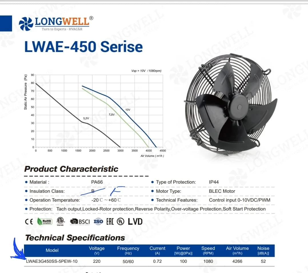
The original catalog reference image showing the Class F insulation requirement update and the expected EC motor physical configuration.
Specifying standby behavior
Fan standby mode is one line in a datasheet and a fleet-wide behavior in the field. In practice, four checks make it deliberate.
- Ask where the stop threshold sits, and whether it exists. Some fans crawl at any voltage above zero; others define a clean standby. Neither is universally right, but fan standby mode should be a choice you made, not a surprise commissioning finds.
- Check the restart behavior with the threshold. A stop level without a defined wake level invites chatter, where a noisy signal near the boundary stops and starts the fan repeatedly. Ask whether the design separates the two.
- Verify your controller floor against the fan threshold. A controller whose minimum output is 1.5 V will never park a fan that stands by below 1.2 V. The two numbers come from different datasheets and meet for the first time in your product.
- Decide what standby should mean at system level. For a condenser synced to a compressor, stop is right. For a space needing minimum ventilation at all times, a defined floor speed is right instead. The fan follows whichever you specify.
See our axial fans range, the EC axial fans section, or condenser fans.
Questions about standby thresholds
Is standby the same as the fan being off?
Electrically no. In standby the control electronics stay awake, watching the signal, while the motor holds still. That is what allows an instant restart when the voltage rises, without the inrush and delay of a cold power-up through a relay.
Why not let the fan run as slow as the signal asks?
Because very low speed delivers almost no air into real system resistance while still wearing bearings and drawing power. Outdoors it adds wind vulnerability, since a crawling impeller can be stalled or reversed by gusts. A defined stop avoids all three.
What happens if the control signal is noisy near the threshold?
A single hard threshold would chatter, stopping and starting with every ripple. Separating the stop and restart levels gives the boundary hysteresis, so the fan commits to each state. It is worth asking any supplier how their threshold handles this.
Does standby save real energy on a condenser?
Yes, in the hours that matter least for cooling and most for the bill. Partial-load and night operation dominate a condenser year, and a fan that parks cleanly instead of crawling converts those hours from waste into genuine zero, across every unit installed.
Technical Documentation & Resources
Got a duty point you need matched?
Tell us the airflow, the pressure and the space you have. Then we mark your duty point on a tested curve and send the drawing back. Meanwhile samples and custom spec sheets take up to 90 days. Since 1990 we have supplied OEMs across HVAC, refrigeration and industry.
Browse Related Products:
🏆 ISO 9001 / ISO 14001 / ISO 45001 | CE (TÜV) | UL/ETL | ATEX Zone 21/22 | AMCA 210/211 / ISO 5801 tested
Choose the right axial fan
Longwell manufactures 1,086 axial fans in-house. Send airflow, static pressure and voltage — an engineer replies with a matching model, performance curve and price within one working day.