Fan performance is often reduced to a few familiar readings: speed, current, input power, sound or a maximum value from a catalog. Those readings matter, but they do not describe installed airflow by themselves. The air path, system resistance, operating point, test method and control state all affect what the equipment is actually doing.
This guide follows the five myths demonstrated in the video and turns them into practical checks for fan selection, commissioning and maintenance.
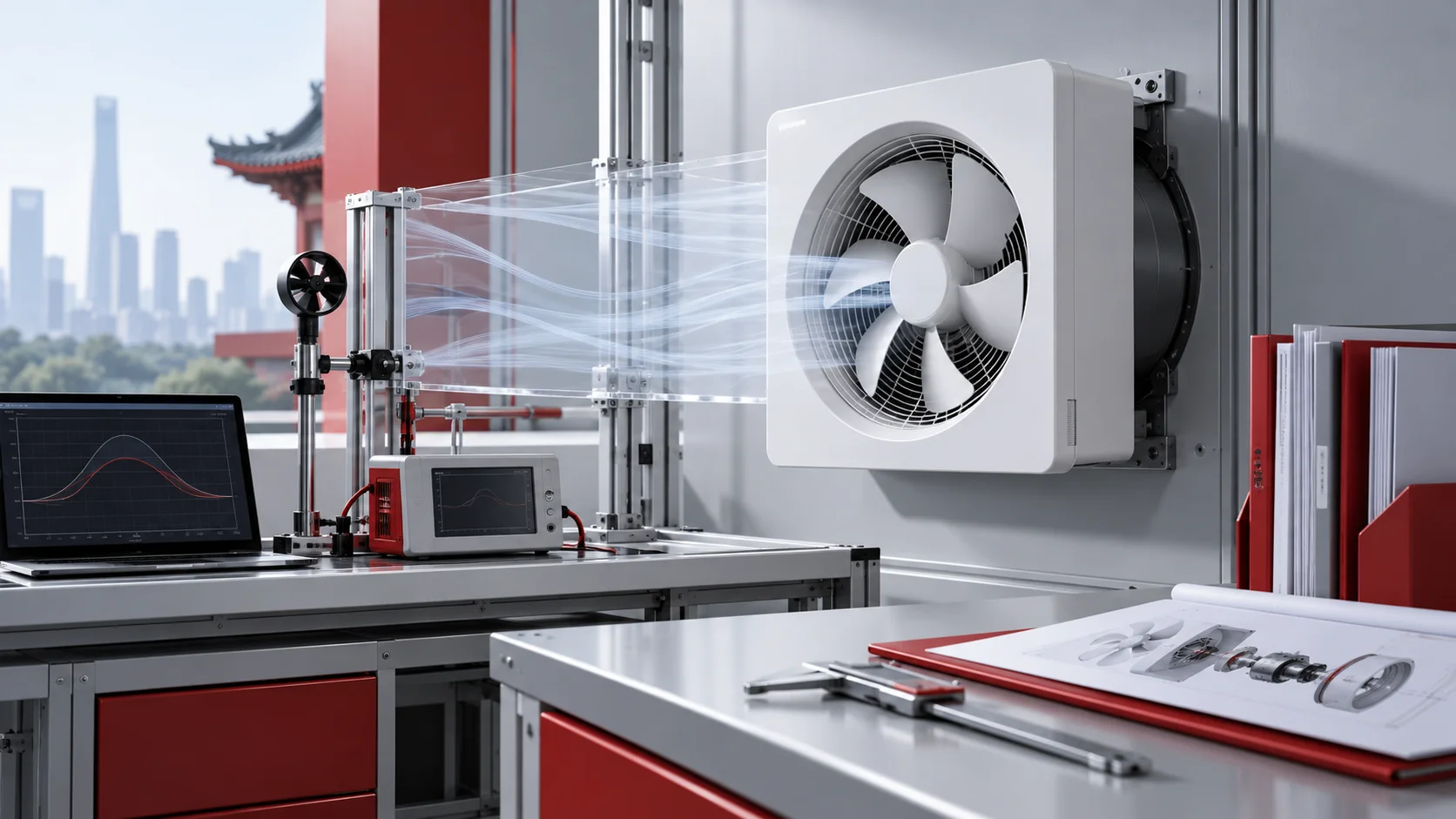
What the fan test setting can—and cannot—show
A controlled test setting helps engineers observe how a fan responds when resistance, speed or arrangement changes. It does not make every displayed value interchangeable with airflow. Each instrument has a defined purpose, and its reading must be interpreted with the test configuration and the fan curve.
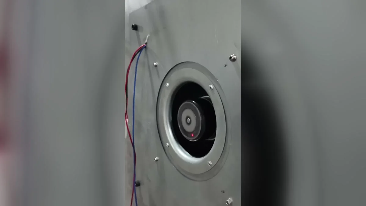
This frame shows a general fan-performance test setting only. It does not identify a fan model, specification, measured result or certified value.
Myth 1: A fan delivers one fixed airflow
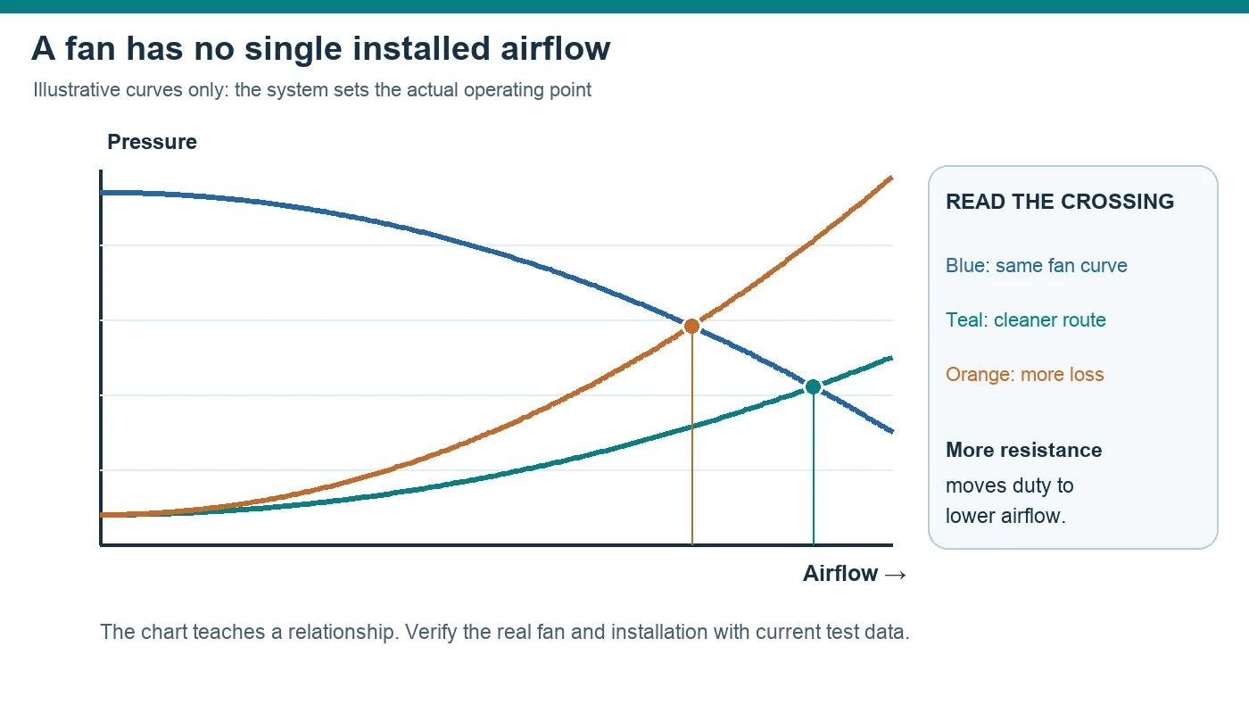
A fan does not push the same airflow into every system. Its operating point moves according to the resistance presented by filters, coils, guards, ducts, bends, dampers and equipment geometry. Even when the fan and commanded speed remain unchanged, modifying the air path can change both airflow and pressure.
The useful question is therefore not, “What is the fan’s airflow?” but, “What airflow will this fan deliver at the pressure required by this system?” The answer comes from the intersection of the fan performance curve and the system resistance curve. This guide to reading fan performance curves explains that relationship without treating either curve endpoint as the installed duty.
Myth 2: RPM, current, watts or sound directly measure airflow
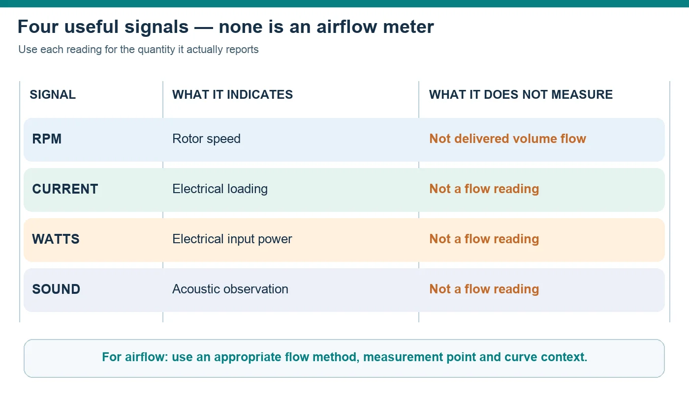
Speed indicates how quickly the rotor turns. Current and input power describe electrical behavior. Sound is an acoustic observation affected by the fan, airflow, mounting structure and surroundings. None of these is a direct airflow measurement.
A change in one reading may suggest that the operating condition has changed, but it does not identify delivered airflow without a validated relationship to the specific fan and installation. The same speed can produce a different operating point when system resistance changes. Electrical readings can reflect motor load, control behavior or supply conditions rather than airflow alone.
What a defensible airflow check requires
Direct airflow assessment needs an appropriate measurement method, a defined measurement location and a known flow area or calibrated test arrangement. The result should be checked against the fan curve and the expected pressure condition. Instrument placement, uneven velocity profiles and inlet or outlet disturbances can affect the reading.
For routine monitoring, indirect signals can still be useful as trends. They should be described as indicators, not silently relabeled as measured airflow.
Myth 3: Fan laws work without limits
Fan laws are valuable engineering relationships, but they depend on similarity. They are most reliable when the same fan geometry, comparable air properties and a similar operating regime are maintained. They are not a blanket promise that every change in speed, wheel size, installation or fluid condition will follow an ideal projection.
Extrapolation can become unreliable outside the tested curve, after major geometric changes or when the surrounding system changes. Motor and controller limits remain relevant too. Use a fan-law estimate to form a hypothesis, then confirm the proposed duty with current performance data and, where needed, an appropriate test.
Why the system curve still matters after a fan-law estimate
A calculated shift in the fan curve does not establish the new operating point by itself. The shifted curve must still meet the system curve. If a damper moves, a filter loads or a duct path changes, the system curve changes as well. A useful review keeps the fan-side assumption and the system-side assumption visible instead of presenting one calculated value as a guaranteed result.
Myth 4: Two fans automatically double pressure or flow
Adding a second fan changes the available combined curve; it does not automatically double the installed result. Fans in series tend to extend pressure capability, while fans in parallel tend to extend flow capability. The actual gain depends on the individual curves, how evenly the fans share the duty and where the combined curve intersects the system curve.
Restrictions, unequal inlet conditions, interaction between discharge streams and dissimilar control commands can reduce the expected benefit. The arrangement must be evaluated using its combined curve and actual air path rather than simple arithmetic.
Series and parallel arrangements need their own operating-point review
A combined arrangement should be evaluated across the intended control range, including conditions where one fan is unavailable or running differently from the others. Engineers should check load sharing, backflow risk, stability and the behavior of the complete air path. Before selecting an array, this overview of how axial and centrifugal fans differ helps separate fan architecture from series or parallel arrangement.
Reviewing the Longwell centrifugal fan families can be a family-level starting point where that architecture warrants evaluation. It is not proof that a listed fan fits a specific duty; the array and system still have to be assessed together.
Myth 5: A stopped fan is safe to work on
A stationary-looking fan is not proof that hazardous energy has been isolated. The impeller may still be coasting down. Moving air can drive it from the opposite direction, a condition often called windmilling. Stored electrical or mechanical energy may remain, and automatic controls may issue a restart command.
A software stop, controller command or zero-speed request is an operating instruction, not an energy-isolation procedure. Before access, servicing or obstruction removal, follow the equipment’s established isolation process, account for every relevant energy source, prevent automatic restart and verify the safe state using the applicable site procedure. Visual observation alone is insufficient.
A practical review before selection or commissioning
- Define required airflow and pressure as one duty point.
- Record filters, coils, guards, ducts and other resistance sources.
- Use RPM, electrical readings and sound only for their stated purposes.
- State the assumptions and similarity limits behind fan-law estimates.
- Evaluate series or parallel fans with a combined curve and system curve.
- Review inlet, outlet, mounting and control interactions.
- Treat software stop and energy isolation as different states.
The engineering takeaway
These myths share one underlying mistake: replacing a system-level question with a single convenient reading. Reliable fan decisions come from matching the fan curve to the air path, measuring the quantity actually needed, respecting the limits of scaling relationships and separating operational commands from verified isolation.