Solving the 1100 mm Span Challenge for HVAC Units
The customer brought us a tough mechanical task. They needed a custom wide span cross flow impeller. This wide span cross flow impeller had to be 1100 mm long and 200 mm wide. Wide HVAC units and air curtains need a wide span cross flow impeller to move air evenly across large openings.
Therefore, engineers often pick tangential impellers for these jobs. However, any wide span cross flow impeller near a metre causes major structural problems. The customer asked for a mixed material design to fix this. First, they wanted a solid 45# steel central shaft.
Next, they picked aluminum for the blades. This choice keeps the outer spinning weight very low. Furthermore, the blower had to run at 1000 RPM. At this speed, tiny size errors cause severe shaking.
Therefore, the blueprints set a strict runout limit. Both radial and axial runout had to stay under 0.5 mm across the whole length. Finally, the job needed precise two-point dynamic balancing. The leftover unbalance had to stay under 0.45 g.
Engineers using this gear must usually meet IEC/EN 60335 safety rules. They also need to meet UL 507 for electric fans. Buyers often test the final airflow to AMCA 210-16 methods too.
Shaft and Rotor Materials for a Wide Span Cross Flow Impeller
Engineers face a tough choice when building an 1100 mm rotor. First, we thought about an all-aluminum design. Extruded aluminum shafts keep the total weight low. They also make the build process much simpler.
However, we rejected the all-aluminum idea. The risk of bending was too high. A one-meter aluminum shaft spins at 1000 RPM. It will bend in the middle from its own force.
Consequently, this bending breaks the strict 0.5 mm limit. It ruins the motor bearings far too early. Instead, we agreed to the customer’s request. We used a 45# steel central shaft.
The 20 mm steel shaft provides high strength. It keeps the spin axis perfectly straight across the 1100 mm gap. This choice had a mechanical cost. The steel shaft makes the whole rotor heavier.
Therefore, this forces the buyer to use a stronger motor. It needs higher starting torque and more power. Even so, this trade-off keeps the unit safe in the field.
Building the Wide Span Cross Flow Impeller
The metal cross flow impeller uses 52 separate aluminum blades. These blades create even static pressure. Meanwhile, these thin aluminum strips need strong internal support. If not, they will twist under force.
Therefore, we added 11 aluminum center discs along the internal shaft. We spaced these discs exactly 98.9 mm apart. So, this tight spacing stops the long blades from bending under air pressure. Furthermore, we looked at how to attach the blades and discs.
Welding aluminum creates hot spots. These hot spots often warp the final part out of shape. By contrast, we used stainless steel core pull rivets for the metal cross flow impeller. This cold fixing method stops heat damage completely.
Finally, our team applied two-point dynamic balancing on the finished rotor. We placed the balance weights exactly within 60 mm of both ends. Consequently, the rotor easily stays under the 0.45 g unbalance limit at 1000 RPM.
Technical Specifications
| Impeller Diameter | Nominal 200 mm (Outer edge Ø 204 mm) |
| Overall Length | 1100 ±1 mm |
| Shaft Left Extension | 70 mm |
| Shaft Right Extension | 100 mm |
| Shaft Diameter | Ø 20 mm |
| Keyway Dimensions | 6 mm width x 35 mm length x 3 mm depth |
| Blade Count | 52 |
| Center Discs | 11 pieces |
| Internal Disc Spacing | 98.9 mm |
| Dynamic Balancing Limit | under 0.45 g residual unbalance |
| Test Speed | 1000 RPM |
| Runout Tolerance | under 0.5 mm (radial and axial) |
| Shaft Material | 45# Steel |
| Blade Material | Aluminum Alloy |
| Fasteners | Stainless Steel Core Pull Rivets |
The 98.9 mm disc spacing creates high strength for this build. Furthermore, the 45# steel shaft handles the high torque. A long spinning mass needs this extra support. Therefore, these exact sizes help the rotor run safely. They keep it well under the 0.5 mm runout limit.
Reference: ISO 21940 covers the test method behind these figures.
Technical Documentation
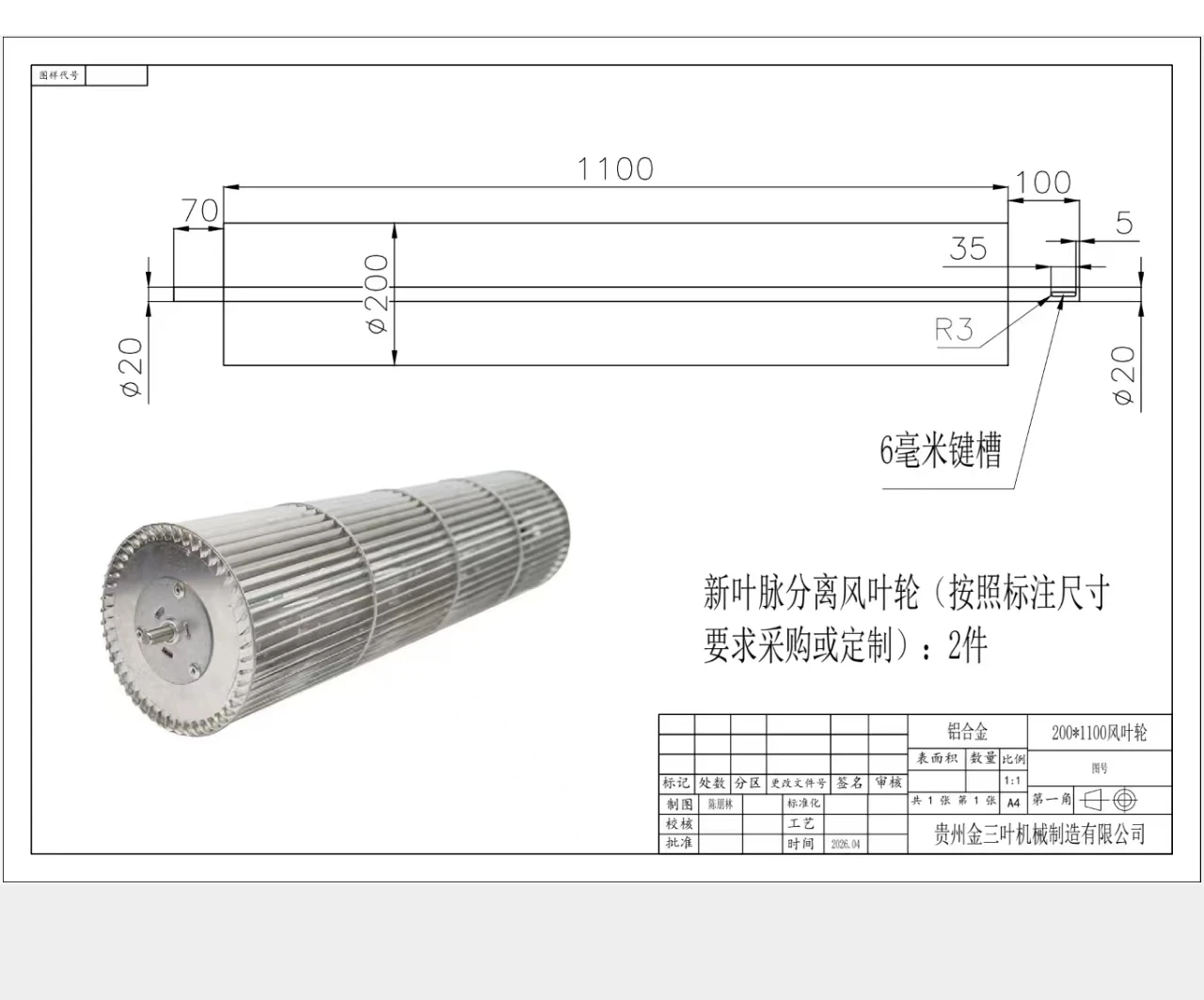
This general mechanical drawing shows the 1100 mm overall length and the 6 mm keyway needed for the motor fit.
Detailed Manufacturing Print and Tolerances
Production teams need this sheet to verify the exact 98.9 mm spacing of the 11 center discs and the rivet spots.
Guidance for Wide-Span Impeller Sourcing
When buying a long metal cross flow impeller for your HVAC project, stiffness matters most. Tiny weight savings matter less. Therefore, check these simple steps before you order:
- First, state your exact running speed for the balance test. Some test a long rotor at 500 RPM. However, if it runs at 1000 RPM, this hides huge balance problems.
- Next, write your exact size limits on your drawings. Shafts over one meter long can bend. Keep radial and axial runout under 0.5 mm. This step protects your mounting bearings.
- Furthermore, check mixed materials closely. A steel central shaft with aluminum blades needs more motor power. Even so, it stops the bad middle bending seen in all-aluminum designs.
- Finally, we make these impellers fully in our Ningbo plant. Therefore, our engineers can change the center disc count for your specific pressure needs. This does not add to the standard 15-30 day lead time.
Related: Cross Flow Fans.
Engineering Questions
Technical Documentation & Resources
Browse our cross-flow fans range, the AC cross-flow fans section, or cross-flow impellers.
Have a Similar Fan Requirement?
Longwell’s engineering team delivers custom spec sheets and samples within 90 days. Since 1990, we have supplied EC fans and blowers to OEMs across HVAC, cold chain, data center, and industrial applications worldwide.
Browse Related Products:
🏆 ISO 9001 / ISO 14001 / ISO 45001 | CE (TÜV) | UL/ETL | ATEX Zone 21/22 | AMCA 210-16 / ISO 5801 tested
Choose the right cross flow impeller
Longwell manufactures 17 cross flow impellers in-house. Send airflow, static pressure and voltage — an engineer replies with a matching model, performance curve and price within one working day.