What the purifier OEM specified
A large maker of premium air purifiers came to us with a concept and a target. Namely a low-noise cross-flow fan running at 2500 RPM. The opening order was 8,000 units.
One limit governed all the rest. The finished low-noise cross-flow fan had to stay under 35 dB(A), always.
That figure is severe for 2500 RPM. It exists because these products sit in bedrooms and offices. In short, a purifier people can hear is a purifier people switch off.
- A 25 kHz PWM signal, since a smart control system drives it.
- A 6-pulse FG tachometer output, so the controller reads speed exactly.
- Sintered metal bushings rather than rubber sleeves, because they last and run true.
- An envelope of roughly 158.8mm by 66mm, since their STEP files fix it.
- Lastly, a firm unit price, because this is a high-volume consumer product.
The customer sending STEP models for the side plates is worth noting. Evidently they had already designed the surrounding mechanics. Consequently our fan had to fit their concept, rather than the reverse.
Building a low-noise cross-flow fan at 2500 RPM
Basically the whole engineering problem fits in one sentence. Namely, reconcile 2500 RPM with under 35 dB(A).
Why those two numbers fight each other
Low-noise cross-flow fan design starts here. Fan noise climbs steeply with tip speed, and 2500 RPM is not slow. Consequently getting under 35 dB(A) means removing every other noise source, since the air noise alone eats most of the budget.
Three sources dominate. Firstly imbalance, then bearing friction, and finally turbulence where air leaves the wheel.
Bearings
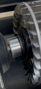
Notably the customer specified sintered metal bushings, and they were certainly right. We used oil-impregnated sintered bronze, which runs with low friction and wears well.
Rubber sleeve bearings start quieter, yet they wear, and the shaft begins to wander. On a wheel turning at 2500 RPM, a wandering shaft becomes audible quickly.
Balance
We balance every impeller to G2.5 grade. That is far tighter than the G6.3 usual for commercial fans. At this noise target, however, it is not optional.
Control
Here the motor is a brushless EC type. It takes the 25 kHz PWM signal directly and returns the 6-pulse FG output their controller expects. Consequently no interface board sits between our low-noise cross-flow fan and their electronics.
How the noise figure is guaranteed
The part matters most, and it is a manufacturing answer rather than a design one.
Every single unit goes through an automated end-of-line test, including an acoustic measurement in a calibrated chamber. Anything at or above 35 dB(A) never gets packed. Meanwhile the result is logged against the serial number.
Designing a quiet fan is achievable. Guaranteeing the eight thousandth one is also quiet is a different problem. Frankly, testing all of them is the only honest way to solve it.
Technical Specifications
Meanwhile the acoustic line is what everything else serves. Read the bearing and balance choices as consequences of a low-noise cross-flow fan target.
| Model Number | LWCD-50150MN-11-00 |
| Fan Type | Cross-Flow Fan (Tangential) |
| Motor Type | Brushless EC (Electronically Commutated) |
| Rated Speed | 2500 RPM |
| Acoustic Noise | < 35 dB(A) |
| Control Input | PWM (Frequency: 25 kHz) |
| Speed Feedback | FG Signal (6 Pulses per Revolution) |
| Bearing System | Sintered Metal Bushings |
| Overall Dimensions (L x H) | ~158.8 mm x 66.0 mm |
Technical Documentation
The following technical files were produced and approved during the project development cycle. They form the final deliverable set for the LWCD-50150MN-11-00 model.
LWCD-50150MN-11-00.pdf
The main specification sheet contains the fan’s performance data, electrical characteristics, and mechanical dimensions, used by system integrators and quality assurance engineers.
LWCD-50150side plate.dwg
Here the dWG drawing provides the exact geometry of the side plate for mechanical engineers integrating the fan into the final product chassis.
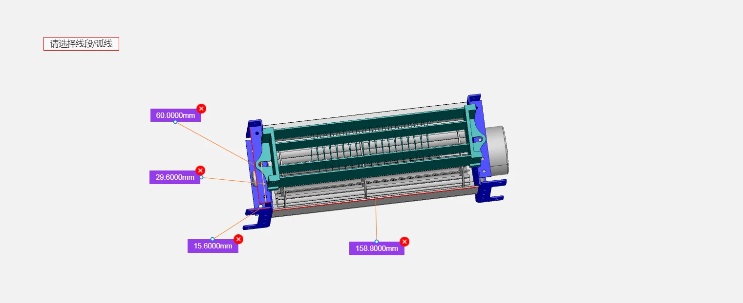
This CAD view highlights the overall assembly dimensions, critical for confirming fit within the customer’s application housing.
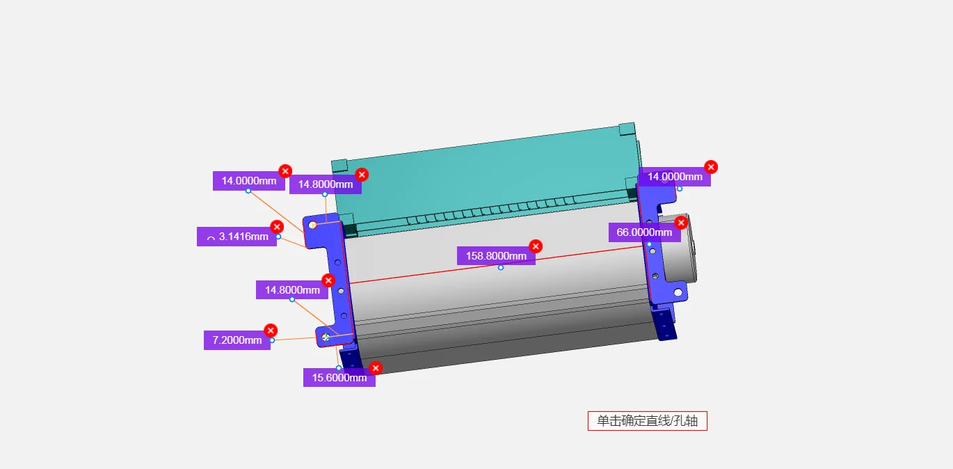
Above, the detailed view provides specific dimensional data for mounting points and clearances, essential for the mechanical design team.
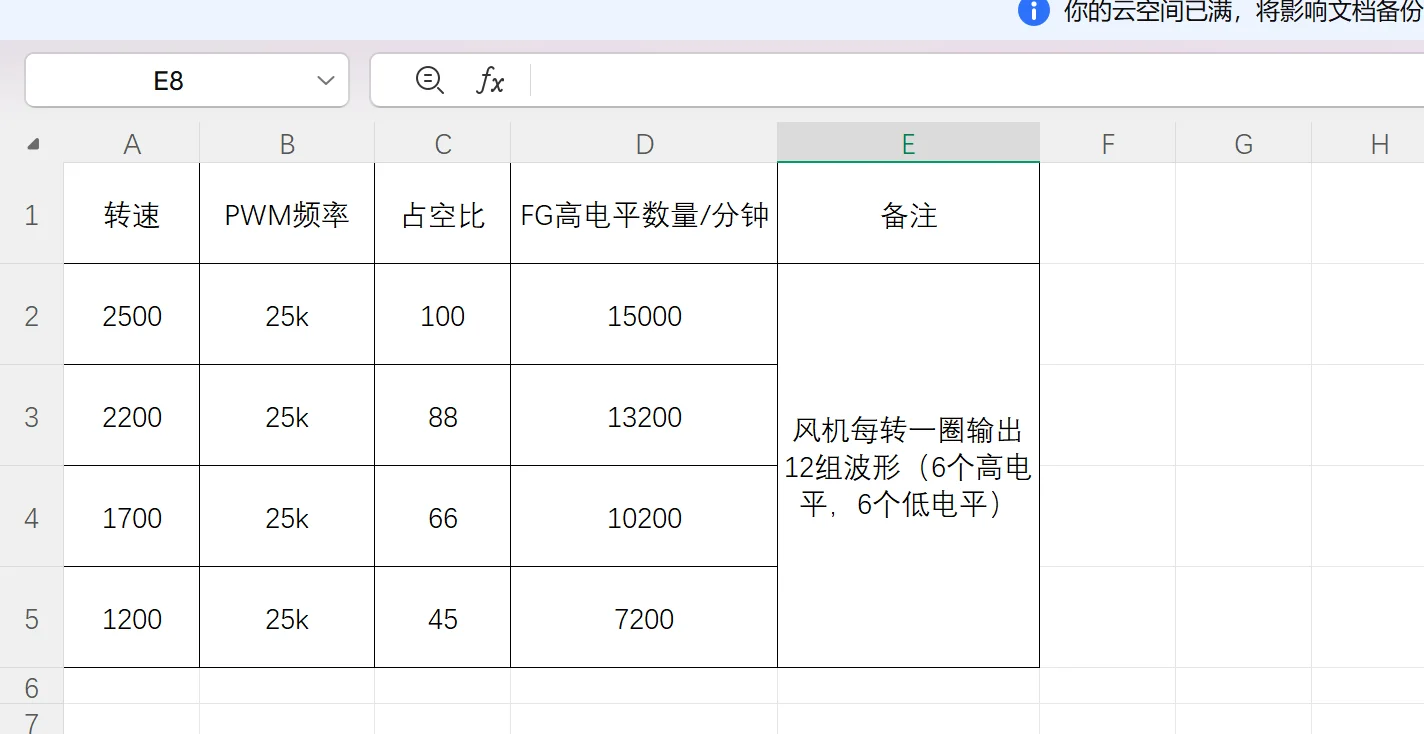
The PWM control mapping table defines the relationship between duty cycle percentage and fan RPM, a necessary reference for firmware and software developers.
Why the OEM developed it with us
For a high-volume consumer product, four things made this work.
- A custom fan inside one quarter. The client needed a unique assembly rather than a catalog part. Our 90-day NPI process covered design, prototyping and testing. European rivals commonly quote 12 to 18 months for the same thing.
- Engineering depth at a consumer price. Hitting a strict noise target on a product with a fixed unit cost needs both skills at once. Making everything ourselves is what lets the balancing, the testing and the price coexist.
- Supply that scales. Eight thousand units, with more to follow, needs certainty. Making EC motors, controllers and metal stampings ourselves gave the grip on quality and timing a mass production ramp needs.
- Design partnership, not order taking. The project began with the customer concept and STEP files. Afterwards our team used CFD and design-for-manufacture work to turn it into something that performs and builds the same way every time.
Browse our cross-flow fan range, or the DC cross-flow fan series. Balance quality grades are defined in ISO 21940.
Questions about control and acoustics
How far can the PWM control be customized?
Here the standard configuration is 25 kHz PWM with a linear speed response to duty cycle, plus 6-pulse-per-revolution FG feedback. For new projects, our 90-day NPI process accommodates different PWM frequencies, non-linear speed curves and alternative tachometer pulse counts to match your controller.
How is the acoustic figure actually guaranteed?
Through multi-level quality control rather than a design claim. Every impeller is dynamically balanced to G2.5 grade, and 100% of finished units go through an automated end-of-line acoustic measurement in a calibrated chamber before packing. Each result is logged against the unit serial number.
What bushings are used, and what life do they give?
Oil-impregnated sintered bronze, picked for low friction and good wear. Accelerated life testing sat outside the scope of this project. Even so, our standard design target for this bearing system is an L10 life above 30,000 hours at 40C.
Why balance to G2.5 rather than G6.3?
Because unbalance makes vibration, and vibration in a plastic-bodied appliance radiates as noise from the panels rather than the fan. At 35 dB(A) there is no headroom for that. G6.3 suits a plant room. A bedroom appliance, by contrast, needs the tighter grade.
Have a fan requirement like this one?
Send the datasheet you are working against, or simply the duty point. Then our engineers tell you what fits and what does not. Meanwhile custom spec sheets and samples take up to 90 days. Since 1990 we have been building fans for OEMs worldwide.
Browse Related Products:
🏆 ISO 9001 / ISO 14001 / ISO 45001 | CE (TÜV) | UL/ETL | ATEX Zone 21/22 | AMCA 210/211 / ISO 5801 tested
Choose the right cross flow fan
Longwell manufactures 495 cross flow fans in-house. Send airflow, static pressure and voltage — an engineer replies with a matching model, performance curve and price within one working day.