Replacing a CBM-7/7 With a Custom double inlet centrifugal blower
A commercial ventilation maker faced a strict safety problem when updating their equipment. Meanwhile, they needed a specific double inlet centrifugal blower. This custom fan had to replace a Soler & Palau CBM-7/7. Therefore, the original unit runs on a 230V, 50Hz power supply, delivering 1000 to 1300 cubic meters per hour of airflow.
Target static pressure hits exactly 305 to 300 Pascals. Also, the single-speed motor spins at 1354 RPM. It carries an IP44 protection rating to resist splashing water. Next, we looked closely at the physical limits.
The double inlet centrifugal blower lives inside a stainless-steel cabinet. In practice, maintenance workers access this cabinet often, so exposed high-speed blades present a huge danger. Therefore, the customer demanded double-sided wire mesh covers. Meanwhile, these strong metal guards must sit directly on the air inlets.
Furthermore, internal space was extremely tight. Therefore, the existing housing has a 224-millimeter discharge width. Its mounting flange measures exactly 286 by 190 millimeters. In practice, our engineers reviewed the original drawings to replicate the mounting points perfectly.
The double inlet centrifugal blower features eight eight-millimeter holes. As a result, these mounting holes sit on exact centers measuring 258 millimeters by 162 millimeters. Any new fan had to match this hole pattern precisely. Meanwhile, the total width could not exceed 319 millimeters from the far edge to the junction box. Finally, the design had to meet strict touch-protection standards without losing internal air pressure.
Designing the Replacement Solution
Engineers must balance safety against airflow. First, we considered an open fan. We rejected this immediately. Therefore, workers need finger protection right at the inlets. Second, we evaluated standard flat finger guards. In practice, we rejected this option too. Flat guards sit too close to the spinning blades. As a result, they cause heavy air turbulence. That turbulence cuts airflow and creates loud noise.
Instead, we chose a convex mesh design for our new blower. We domed the wire mesh outward. Moreover, this pushes the metal rings away from the impeller. Consequently, air flows smoothly into the scroll housing. Meanwhile, the convex shape preserves the 1000 to 1300 cubic meters per hour airflow target.
Matching the Electrical Setup
We also had to match the wiring perfectly. Therefore, the old CBM-7/7 used an external black box. This box held the terminal block. In practice, it also contained a five-microfarad capacitor rated for high voltage. Therefore, we added an identical side-mounted box to our LWFA-E-200-02 model. As a result, we routed a heavy four-core cable from the motor into this box. The terminal block provides easy connections for the blue, black, brown, and yellow-green wires. Moreover, workers can wire the new unit exactly like the old one. The maximum current stays safely under 1.8 amps.
Evaluating the Engineering Trade-Offs
However, this safe double inlet centrifugal blower came with specific costs. First, the convex mesh adds physical width. The total assembly measures 319 millimeters across, which is wider than a bare fan. In short, second, the custom metal mesh creates a materially higher cost. Welding the domed wire to exact safety specifications takes extra production time. Even so, the customer easily accepted these costs. They gained complete maintenance safety. Meanwhile, they also kept their required 305 Pascals of static pressure. The final 250W motor hits the 1354 RPM target easily.
Technical Specifications
| Parameter | Specification |
|---|---|
| Model | LWFA-E-200-02 |
| Voltage | 230 VAC |
| Frequency | 50 Hz |
| Airflow | 1000 – 1300 m³/h |
| Static Pressure | 305 – 300 Pa |
| Power | 250 W |
| Current | 1.8 A max |
| Speed | 1354 ±10% RPM |
| Capacitor | 5 uF |
| Protection Type | IP44 |
| Operating Temp | -20°C to +40°C |
| Discharge Width | 224 mm |
| Mounting Flange | 286 mm x 190 mm |
| Hole Spacing | 258 mm x 162 mm |
| Hole Diameter | 8 mm |
| Total Width | 319 mm |
| Housing Height | 369 mm |
The 286 by 190 millimeter mounting flange dictates the mechanical fit. Therefore, matching the 1354 RPM speed ensures the precise airflow. The IP44 rating protects the motor from splashing water. In practice, a five-microfarad capacitor provides the correct starting torque. Finally, the exact 224-millimeter discharge width guarantees smooth air delivery.
Reference: AMCA 210 covers the test method behind these figures.
Technical Documentation
longwell-wi-6952895469-technical-doc-01.pdf
This dimensional drawing details the LWFA-E-200-02 mounting flange, exact hole spacing, and double-sided mesh cover configuration.
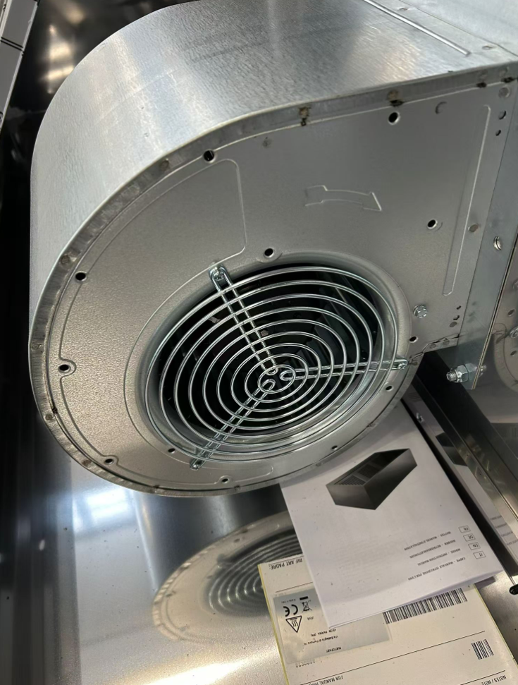
This field image displays the existing blower installed inside the stainless-steel cabinetry, highlighting the necessity of inlet guards. As a result, this image shows the original Soler & Palau CBM-7/7 model that the customer needed to replace.
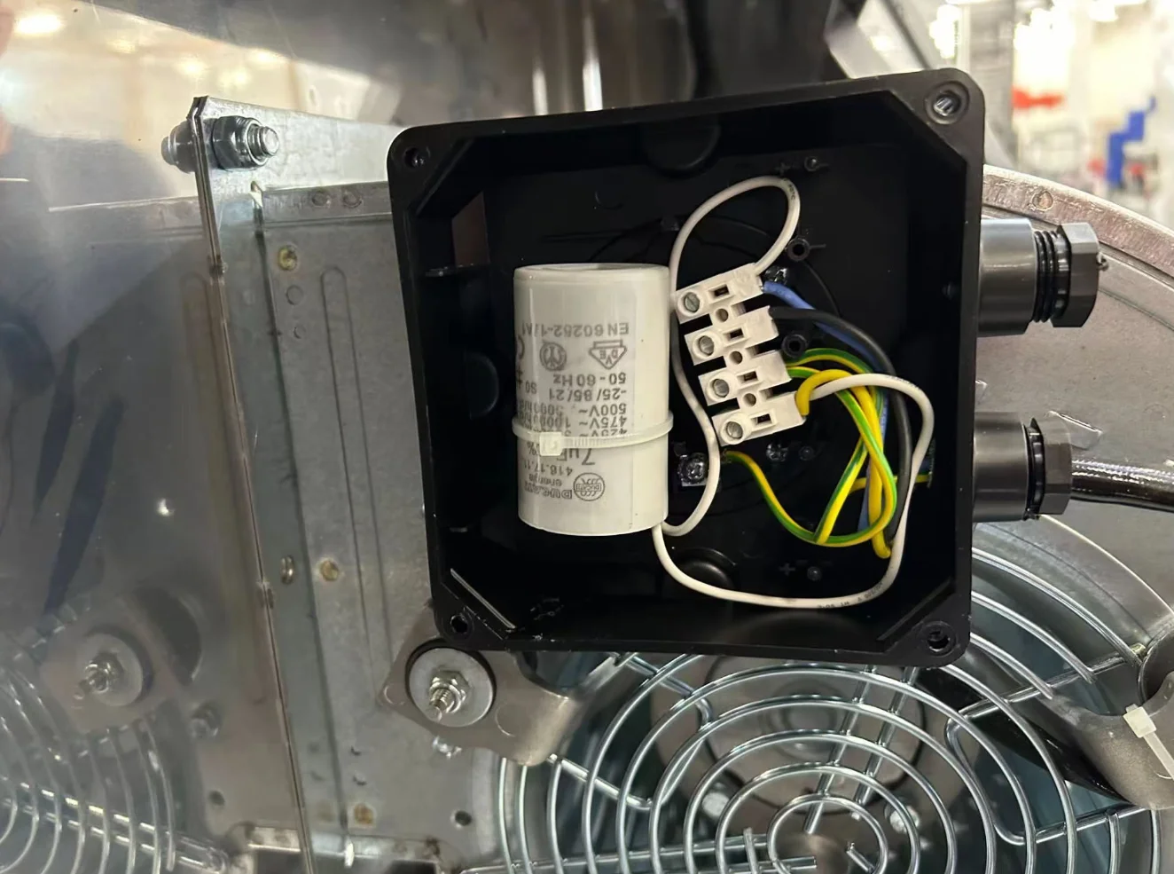
This close-up reveals the internal wiring of the side-mounted junction box, including the five-microfarad capacitor and terminal block layout.
Specifying Your Own Double Inlet Centrifugal Blower
- First, measure your exact mounting flange holes. Moreover, our project used an eight-hole layout spaced at 258 by 162 millimeters. You cannot easily drill new holes in heavy sheet metal, so precise hole centers matter.
- Second, check the physical clearance around your air intakes. In short, convex mesh guards push outward. They will hit cabinet walls if internal space is too tight.
- Next, take clear photos of your terminal block. Besides, this simple step helps the factory match your existing wiring layout exactly.
- Finally, always verify the exact capacitor size. An incorrect microfarad rating will ruin the motor. A 230V fan requires the precise capacitance listed on its nameplate to start reliably.
If you are adding inlet guards, check IEC safety standards to ensure the wire spacing adequately prevents finger ingress for your specific application.
Related: Centrifugal Fans.
Engineering Questions About This Project
Technical Documentation & Resources
Browse our centrifugal fans range, the backward-curved fans section, or forward-curved fans.
Have a Similar Fan Requirement?
Longwell’s engineering team delivers custom spec sheets and samples within 90 days. Since 1990, we have supplied EC fans and blowers to OEMs across HVAC, cold chain, data center, and industrial applications worldwide.
Browse Related Products:
🏆 ISO 9001 / ISO 14001 / ISO 45001 | CE (TÜV) | UL/ETL | ATEX Zone 21/22 | AMCA 210-16 / ISO 5801 tested
Choose the right forward curved centrifugal fan
Longwell manufactures 93 forward curved centrifugal fans in-house. Send airflow, static pressure and voltage — an engineer replies with a matching model, performance curve and price within one working day.