What the OEM asked for
An existing OEM partner in commercial HVAC asked for a plastic cross-flow impeller: 101.5mm in diameter, 580mm long. The message ran to one line, essentially asking us to issue the drawing.
Attachments told the rest. Namely an ordering form for plastic impellers, plus an existing drawing. Evidently this is a practised integrator who knows our range. They simply need a formal drawing, since a fan coil unit is going into production.
Consequently the limits came mostly from the housing, which already existed.
- A 101.5mm diameter and 580mm length, since the housing exists already.
- Plastic build, because weight, noise and cost all favor it.
- Residual unbalance no greater than 0.3g, measured at 1200 RPM.
- A maximum test speed of 1600 RPM.
- Lastly, radial runout under 0.7mm.
Those last three lines describe the noise target without naming it. A 0.3g balance figure usually means the finished unit goes where people sit. In short, the whole spec is about a fan nobody notices.
Specifying the plastic cross-flow impeller
The request was for a drawing. Even so, we start by checking the job really suits the part. Here it does.
Cross-flow is the right architecture
Basically a 580mm length with a small diameter settles it at once. That shape gives the wide, even airflow an FCU coil needs across its whole face. An axial or centrifugal fan, by contrast, bunches the air up. Consequently parts of the coil do no work.
Why not aluminum
We looked at aluminum for stiffness, then rejected it on two counts.
Firstly, 1600 RPM sits well inside what a glass-filled polymer handles. Consequently the extra rigidity buys nothing. Secondly, metal rings. Its noise behavior is worse than filled plastic, which is exactly wrong indoors.
The material that was chosen
So the plastic cross-flow impeller is molded in acrylonitrile styrene with 30% glass fiber, AS+GF30%.
That blend holds its shape and stays stiff enough to stop blade bending at peak RPM. Meanwhile it damps vibration better than metal, which is where much of the quietness comes from.
Finalising the drawing
Our technical team finished the drawing against the LWPI-φ101.5×580-02 revision. That meant checking every making detail. Chiefly the ultrasonic welding used to join the blades, plus the runout tolerances the balance figure rests on.
Ultrasonic welding matters more than it sounds. It joins the blades with no added glue weight. Glue weight, in turn, is exactly the small uneven mass that ruins a 0.3g balance target.
Technical Specifications
Here the balancing line and the material line are the two that matter on a plastic cross-flow impeller. Everything else on this drawing follows from them.
| Parameter | Value |
|---|---|
| Model | LWPI-101.5×580-02 |
| Impeller Type | Cross-Flow Impeller |
| Impeller Diameter | 101.5 mm |
| Impeller Length | 580 mm (±2 mm) |
| Shaft Bore Diameter | 8 mm (+0.022 mm) |
| Material | AS+GF30% (Acrylonitrile Styrene + 30% Glass Fiber) |
| Rotation | CCW (Counter-Clockwise from shaft end) |
| Balancing Specification | ≤ 0.3g @ 1200 RPM |
| Max Test Speed | 1600 RPM |
| Radial Runout Tolerance | < 0.7 mm |
Technical Documentation
The following documents were generated and approved as part of the project deliverables.
LWPI-101.5×580-02 Drawing (PDF)
This is the final approved engineering drawing, providing all dimensional, material, and tolerance data required by a mechanical design engineer for integration into an HVAC unit housing.

Meanwhile the image provides a quick visual reference of the impeller’s key dimensions and construction, useful for procurement managers and assembly line technicians.
Plastic Cross-Flow Impeller Ordering Sheet
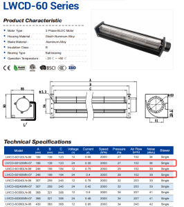
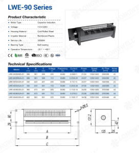
Here the excerpt from Longwell’s plastic cross-flow fan ordering sheet shows the basic parameters of the LW101.5×580-01 model, allowing procurement teams to cross-reference it within the broader product family.
Why the drawing came from us
Behind what looks like a simple drawing request, four things sit.
- Drawings issued promptly. This request moved through our engineering workflow and came back quickly. That same workflow handles genuinely custom designs inside a 90-day NPI cycle, far shorter than imported European brands typically quote.
- Every process is ours. The balance target and the material choice are fixed points for noise. Since molding, tooling and welding all happen in house, we control them on every part rather than inspect them afterwards.
- A direct bill-of-materials advantage. Molding this plastic cross-flow impeller on our own tooling keeps its cost predictable across a production run, with no compromise on the acoustic behavior end users judge the product by.
- Data behind the part. The customer asked only for a drawing. Nonetheless, we test impeller and fan assembly performance in our labs to AMCA 210/211 and ISO 5801 methods, which supports their own design and certification.
Browse our cross-flow impeller range, or the cross-flow fan section for complete assemblies. Appliance safety is covered by IEC 60335-1.
Questions integrators ask
What motor suits this impeller, and can you supply it?
The impeller takes an 8mm shaft, as the drawing specifies. Given the 1600 RPM test speed and the noise target, a SmartEC motor is a good match, since it gives variable speed through 0-10V or PWM. We supply the impeller alone for your existing motor, or a pre-balanced motor and impeller assembly ready to fit.
Is AS+GF30% compliant with RoHS and REACH?
Yes. Every material in our impellers, this one included, complies with RoHS 2011/65/EU and REACH (EC) 1907/2006. We provide full material data sheets and compliance certificates on request, which is what your CE technical file needs.
What lead time and MOQ apply?
For a standard HVAC component like this, make-to-order lead time runs 15 to 25 days at volumes between 100 and 500 units, with an MOQ of 100 for a first production run. Under a frame agreement with a rolling forecast we can set up a stock program shipping in 1 to 5 days.
Why does the balance figure matter more than the airflow figure?
Because airflow is easy to check and hard to get wrong, whereas unbalance appears as noise only after the unit is built. A long, slender impeller is especially touchy. A small mass error at one end acts across the whole rotor rather than as a simple force.
Technical Documentation & Resources
Need the same thing for your own unit?
Give us the numbers and the envelope, and you get a shortlist rather than a catalog. Meanwhile custom spec sheets and samples run to 90 days. Since 1990 Longwell has supplied EC fans and blowers to OEMs in HVAC, cold chain, data center and industrial markets.
Browse Related Products:
🏆 ISO 9001 / ISO 14001 / ISO 45001 | CE (TÜV) | UL/ETL | ATEX Zone 21/22 | AMCA 210/211 / ISO 5801 tested
Choose the right fan impeller
Longwell manufactures 10 fan impellers in-house. Send airflow, static pressure and voltage — an engineer replies with a matching model, performance curve and price within one working day.