Designing a 24V PWM Blower for Restricted Envelopes
The customer brought us a hard packaging problem. Meanwhile, they needed a slim cooling part for a packed chassis. The space limit was absolute. Therefore, the cross-section could not pass 80 by 57 mm, and the whole unit had to stay within 760 mm. So the job needed a custom 24V PWM blower. In practice, it had to spread even air across a long heat exchanger.
Specifically, the system required 365 m3/h of airflow against 28 Pa of static pressure. Environmental demands also dictated the design. Ambient temperatures for this equipment range from -25°C to +60°C. The noise ceiling was set at a strict 46 dB(A).
Crucially, the customer required active thermal management integrated directly into the motor. They needed PWM speed control and an FG tachometer signal output to sync with their existing PCB logic. Compliance was another fixed variable. The final unit needed to meet Insulation Class B standards.
Performance was tested to AMCA 210-16 methods. Meeting all these metrics within a 57 mm height limit restricted the viable diameter of the impeller, forcing us to balance rotational speed against acoustic limits.
Balancing Airflow, Noise, and Motor Control
When configuring this 24V PWM blower, we faced several choices regarding the motor logic and the mechanical structure.
Motor Selection and PWM Integration
Initially, a standard 0-10V analog control motor was considered, as it is standard on the LWCD-45 series. However, the customer’s control board relied on high-frequency digital pulses. We rejected the 0-10V option because adding an external digital-to-analog converter would complicate their PCB layout and increase their assembly time. Instead, we selected a 3-phase BLDC motor configured specifically for PWM input.
This allowed direct integration via a 500 mm, 4-wire setup. Consequently, the custom motor winding and control logic extended the sample lead time slightly. This was the cost of exact integration. Even so, it eliminated the need for external conversion hardware on the customer’s end.
Impeller Geometry and Material Trade-offs
Next, we evaluated the impeller material and bearing system. A plastic impeller would reduce overall weight and rotational inertia. By contrast, an aluminum alloy impeller offers superior rigidity across the 700 mm double-blower span. We opted for 45 mm diameter aluminum alloy impellers paired with a steel and aluminum housing.
This combination prevented flex at the target 2000 RPM, keeping vibration well under acceptable limits. Furthermore, we selected ball bearings over sleeve bearings. Sleeve bearings operate quietly at first but degrade quickly near the +60°C upper ambient limit. Therefore, the ball bearing choice added a minor material cost but ensured long-term reliability under continuous operation. The final configuration delivers 365 m3/h at 46 dB(A), successfully answering the thermal and acoustic constraints.
Technical Specifications
| Parameter | Specification |
|---|---|
| Model | LWCD-45700MN-06-14 |
| Voltage | 24 VDC |
| Current | 0.85 A (±10%) |
| Speed | 2000 RPM |
| Airflow | 365 m3/h |
| Static Pressure | 28 Pa |
| Noise Level | 46 dB(A) |
| Speed Control | PWM |
| Signal Output | FG Tachometer |
| Bearing Type | Ball bearing |
| Impeller Diameter | 45 mm |
| Total Dimensions | 760 x 80 x 57 mm |
| Operating Temperature | -25°C to +60°C |
| Insulation Class | B |
The physical dimensions dictated the dual-impeller design. Since the total length reached 760 mm, a double blower configuration was necessary. This setup maintains structural integrity at 2000 RPM without destructive shaft deflection.
Reference: AMCA 210 covers the test method behind these figures.
Technical Documentation
Download the dimensional drawing and wiring specification. This engineering drawing details the exact 760 mm envelope, the 4-wire color codes, and the mounting plate hole locations required by mechanical engineers.
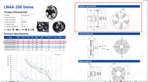
This catalog excerpt outlines the standard base model parameters and materials before the custom PWM control integration.
How to Specify a 24V PWM Blower for Restricted Profiles
When your system demands a custom 24V PWM blower to create a long air curtain, the physical envelope usually becomes the binding constraint. If you face a similar thermal management challenge, secure these details before requesting a quote:
- Measure the absolute maximum cross-section available. A strict 80 by 57 mm envelope restricts the impeller diameter to 45 mm, which directly caps static pressure capability.
- Verify your control logic. Specify whether your board outputs a 0-10V analog signal or a PWM digital pulse. This dictates the exact BLDC motor circuitry we need to install.
- Determine the operating temperature range. An upper limit of +60°C forces the use of ball bearings, altering the acoustic profile slightly compared to sleeve options.
- Send your exact dimensional constraints. Because we manufacture the aluminum impellers in-house, we can adjust the double-blower span precisely to fit specific chassis widths.
Related: Cross Flow Fans.
Engineering FAQs
Browse our blowers range, the exhaust blowers section, or centrifugal blowers.
Have a Similar Fan Requirement?
Longwell’s engineering team delivers custom spec sheets and samples within 90 days. Since 1990, we have supplied EC fans and blowers to OEMs across HVAC, cold chain, data center, and industrial applications worldwide.
Browse Related Products:
🏆 ISO 9001 / ISO 14001 / ISO 45001 | CE (TÜV) | UL/ETL | ATEX Zone 21/22 | AMCA 210-16 / ISO 5801 tested
Choose the right blower
Longwell manufactures 247 blowers in-house. Send airflow, static pressure and voltage — an engineer replies with a matching model, performance curve and price within one working day.