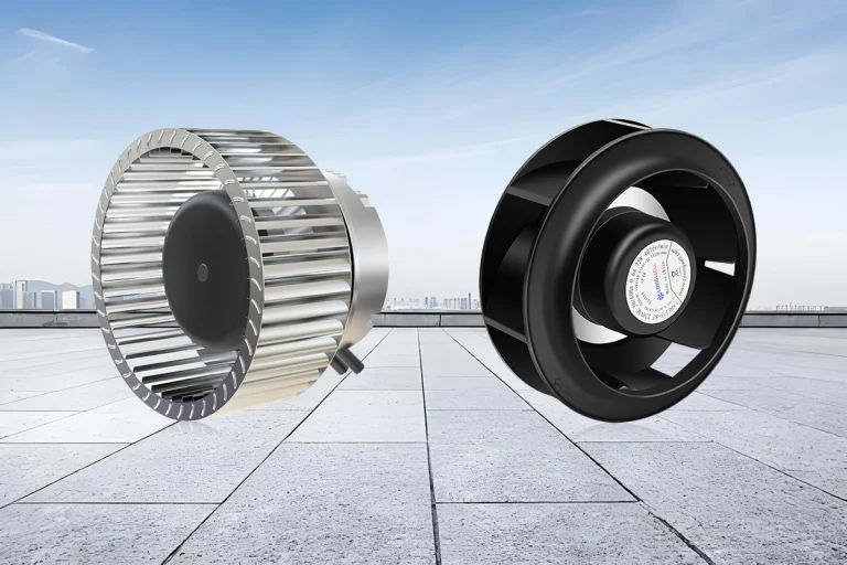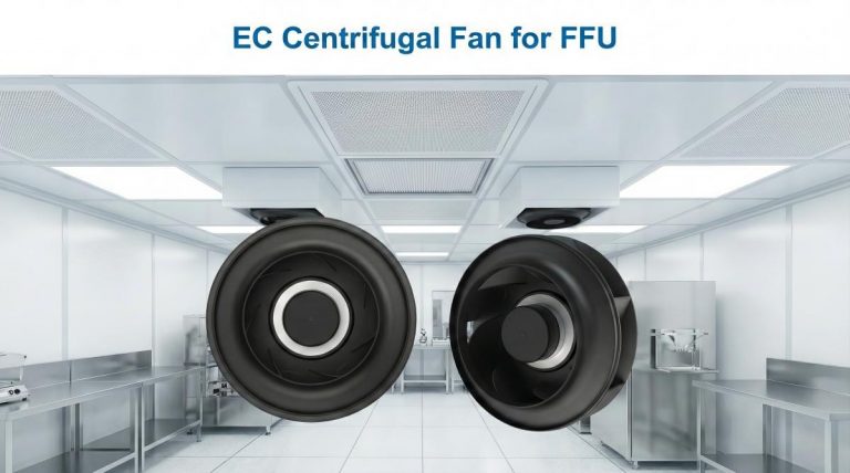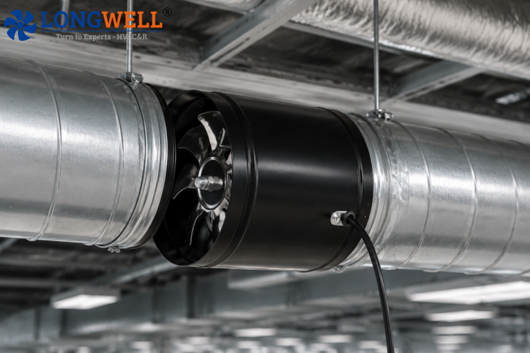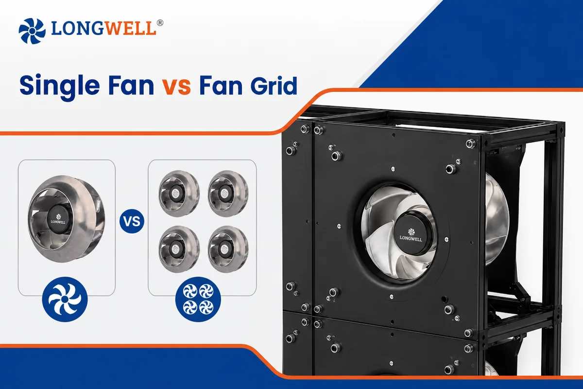
Continuous and consistent airflow is very essential for HVAC projects, air handling units (AHUs), and data center cooling. In most systems, a single fan is selected to provide the required airflow and static pressure for the whole system. But in some cases, fan grid will provide more advantages for operating performance and energy efficiency. So, how to choose between a 560mm single fan and double two 450 fans in a system? You’ll get the right answer in our blog.
What is a Single Fan?
A single-fan system usually contains a large fan to handle the airflow required by the application. For example, an traditional AHU system may use a large belt-driven or direct-driven plenum fans to move air through filters and connected ductwork. Though single-fan system can be a cost-effective option for many cases, it has one drawback. Once the fan failed to work, the airflow is totally lost and the followed maintenance requirements and limited controllability can further make the operating more complex in the long running.
What is a Fan Grid?
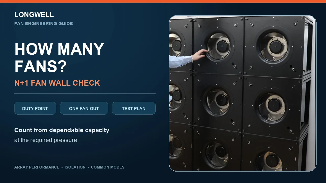
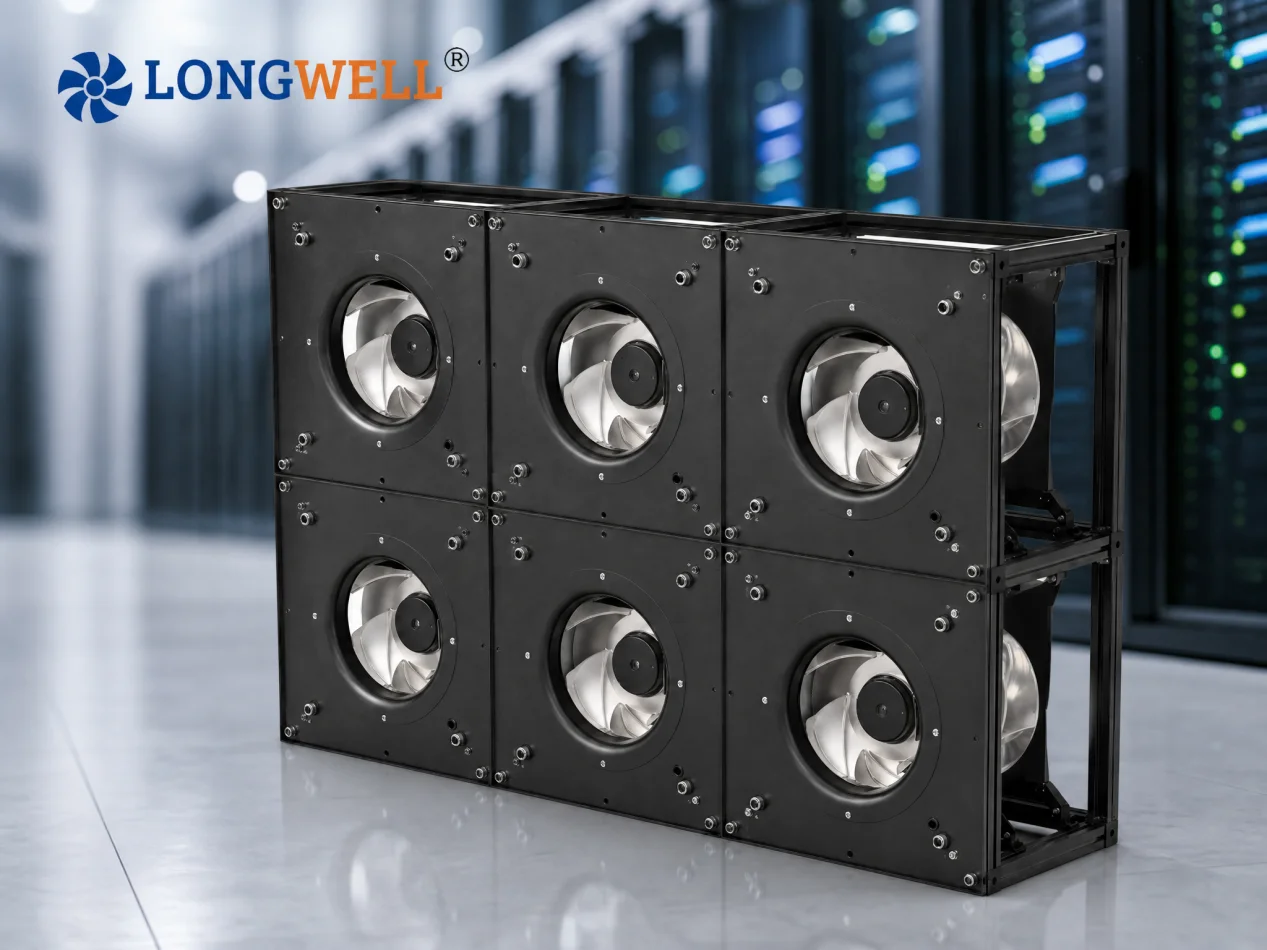
A fan grid is a structure consisting of multiple fans installed parallel to provide required airflow. IT is typically used in applications where high airflow capacity, large air-handling volumes, or flexible airflow control are required. A fan grid breaks the single fan into a wall of smaller, direct-drive EC plug fans mounted in a bulkhead. A fan grid can be configured with two, four, six, eight, or many more fans depending on the application and is often used for large AHUs, data center cooling systems, and other high-capacity ventilation applications.
The three terms describe the same idea with slightly different emphasis:
- Fan wall — the physical bulkhead of fans set into a panel across the cabinet.
- Fan array — the same grid viewed as a parallel electrical/aerodynamic circuit.
- Fan grid / FanGrid — the engineered module kit: identical EC plug fans, mounting frame, sealing plates and central control, typically specified as a replaceable unit.
Single Fan vs Fan Grid: Key Differences
|
Criterion |
Single Large Fan |
Fan Grid (EC plug fans in parallel) |
|---|---|---|
|
Failure mode |
One fan, belt or motor failure stops the whole section |
One module can be isolated; remaining fans speed up and hold design airflow (N+1) |
|
Part-load energy |
Throttled dampers or one fan driven down its curve; belt adds 5–12% transmission loss |
Stage fans off or run all fans slower; no belt loss |
|
Maintenance |
Large motor and impeller handling; belts, sheaves, bearings, greasing, alignment |
Small module swap without taking the AHU offline; sealed-for-life bearings |
|
Retrofit access |
May need a large access opening |
Identical modules fit through standard service openings and doorways |
|
Airflow uniformity |
Scroll discharge is uneven across the coil behind it |
Wide, low-velocity discharge |
|
Noise |
Single high tip speed dominates the spectrum |
Lower per-fan tip speed; A-weighted sound drops with tip speed |
|
First cost |
Lower per unit |
Higher initial costs, typically recovered in 2–3 years on energy |
|
Control complexity |
Simple — one motor, one signal |
Needs load-sharing logic, fault detection and redistribution |
|
Installation |
Simple |
More complex |
|
Applications |
Standard HVAC systems |
Large or critical HVAC/data center systems |
The Physics Behind the Savings
Fan affinity laws: Q ∝ n · P ∝ n² · W ∝ n³
Airflow scales with speed, pressure with speed squared — and power with speed cubed. A fan turned down to 80% speed draws roughly 0.8³ ≈ 51% of rated power. At 75% speed, about 42%.
This cube law is why part-load operation dominates the comparison. Most AHUs and CRAH units run well below design airflow for most hours of the year — data centers commonly operate between 30% and 60% load. A single fan at part load has only one lever: throttle or slow the whole machine down one inefficient curve. A grid has two: slow every fan a little (harvesting the cube law), or stage fans off and run the survivors nearer their best efficiency point.
However, the potential energy savings of a fan grid depend heavily on its control sequence. Running too many fans at very low speed may not be optimal, while operating too few fans at excessively high speed can also increase energy consumption. In other words, the fan grid itself does not guarantee lower energy consumption—the way it is controlled determines how effectively it will operate.
Where Fan Grid Wins?
Data Center CRAH and Fan-Wall Cooling
Data center cooling systems should maintain continuous airflow and the cooling performance can vary with IT load and different environments. This combination makes reliability, part-load efficiency, and controllability critical considerations for CRAH and AHU design. A FanGrid addresses these requirements by combining multiple independently controlled fans with built-in redundancy.
A documented LONGWELL reference project — a 50-fan CRAH FanGrid retrofit at a 2 MW Tier 3 colocation site — replaced legacy belt-drive AC fans running at 1.45 PUE with 5 rows × 10 LWBE3G-500-EC plug fans under Modbus N+1 control: fan energy down 28%, PUE 1.45 → 1.32, and per-fan runtime telemetry feeding the site DCIM.
Hospitals, Pharma and Cleanrooms
Staged service is the argument that closes the sale: isolate and swap one module without taking the AHU offline. Filter-critical and infection-control areas keep airflow while maintenance happens.
Aging AHU Retrofits
The old housed fan, motor and belts come out; a modular fan wall assembles inside the existing cabinet, often in the same footprint. LONGWELL FanGrid kits ship as form-fit replacement packages — modular steel frame, identical EC plug-fan modules, adaptable sealing plates, and a central controller that integrates with the existing BMS. Compared with conventional forward-curved belt-driven fans, the upgraded fan wall improves efficiency by roughly 20–50%, with typical whole-project payback of 2–3 years.
Offices, Airports and Large Commercial Buildings
Lower part-load noise, better IAQ control and markedly lower energy in variable-occupancy profiles.
Where a Single Fan Still Wins?
- High-static-pressure systems
Small plenum fans or selected EC plug fans develop limited pressure. Where the duty point sits beyond what an EC plenum fan can reach — long duct runs, heavy filtration, high-resistance coils — a single housed fan remains the better choice.
- Small, low-pressure, constant-volume units
If the unit runs 24/7 at one duty point, redundancy and turndown add nothing, and the single fan is cheaper and simpler to control and maintain. At constant full flow, the efficiency gap also narrows — belt losses are a few points, not a canyon.
- Price-driven standard AHUs with routine belt service
If the maintenance team already services belts as part of normal operations and downtime is tolerable, the lowest first cost still buys the unit.
EC FanGrid Designs – 4 Things to Avoid
- Don’t omit backdraft dampers
Each fan needs a backdraft damper that closes when the fan stops. Without it, running fans push air backward through the idle or failed module and recirculate flow inside the plenum — the N+1 redundancy you paid for disappears the first time a fan trips. An array specified without dampers is a problem to flag at design review, not at commissioning.
- Don’t Treat Redundancy as a Paper Specification
N+1 counts only if the control strategy can detect a fan trip and redistribute airflow. Commission with a one-fan-down test: confirm the damper closes, the surviving fans ramp up, and the unit holds design airflow. Balancing every fan running does not prove redundancy.
- Don’t Use Inefficient Load-Sharing Logic
One of the main advantages of an EC FanGrid is its ability to adapt capacity to changing system demand. Poor control logic, however, can undermine that advantage.
Running too many fans at very low speed may increase the number of operating components without delivering the most efficient overall operating point. Conversely, running too few fans at very high speed may increase power consumption, noise, and operating stress.
- Don’t Ignore Inlet Conditions and Power Quality
Fan performance can be affected by non-uniform inlet airflow. Obstructions near fan inlets distort flow and can cost double-digit efficiency points. The fan array should therefore be evaluated together with the surrounding airflow path. On large EC installations, budget for line filters or harmonic mitigation if the facility power is sensitive — hospitals in particular.
Spec Checklist: What to Put in the RFQ?
- Module size and quantity
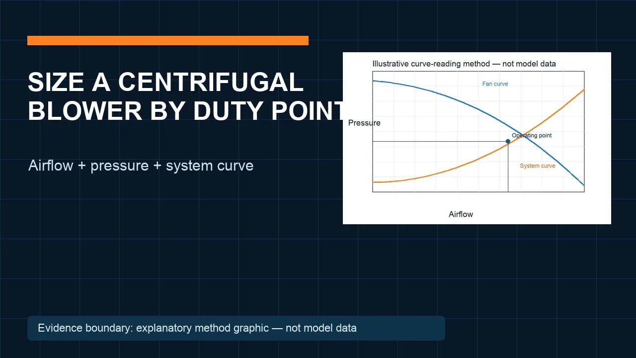
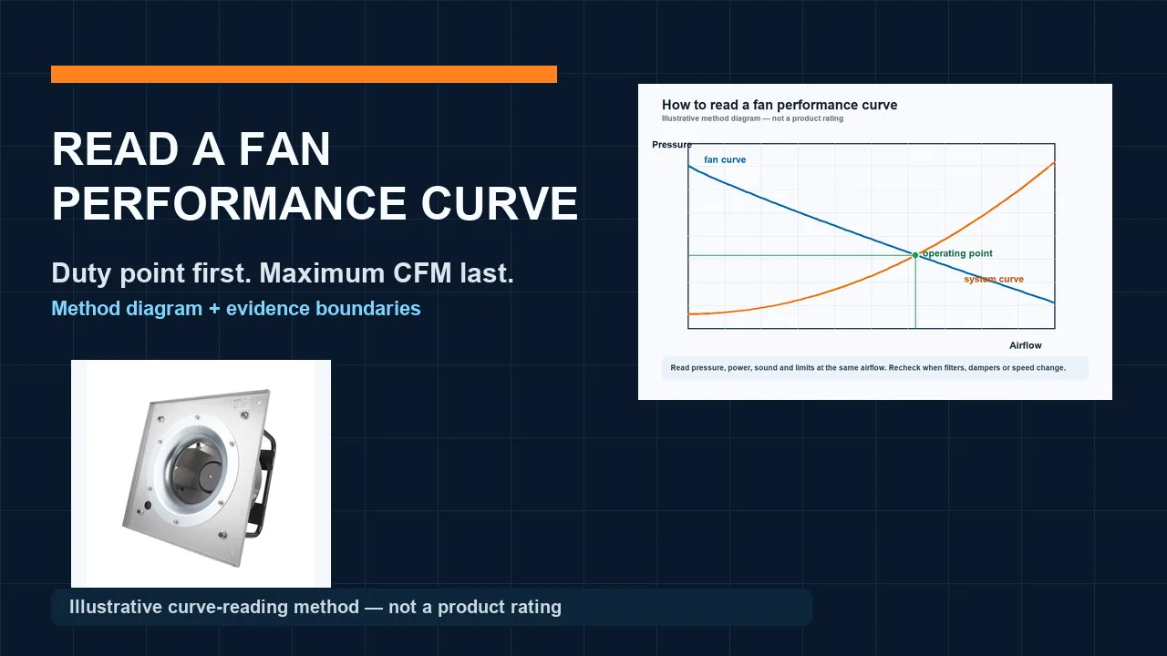
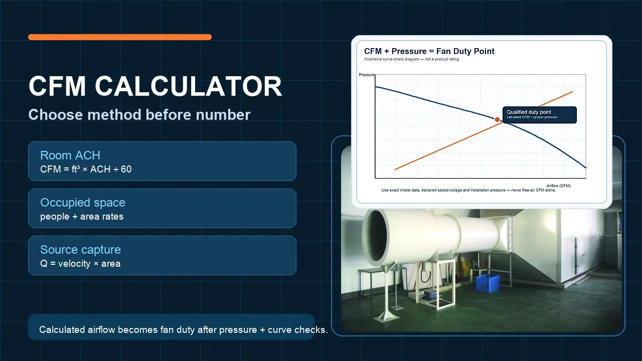
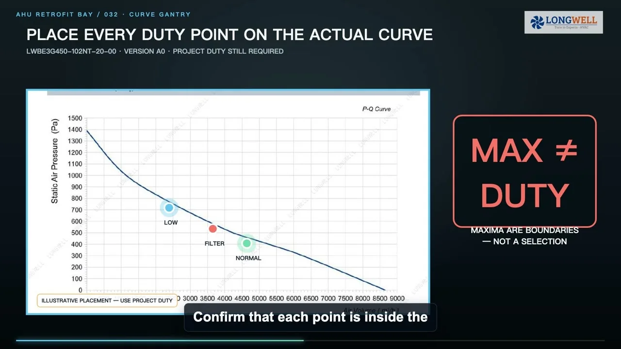
- Airflow and static pressure
- Voltage: single-phase 110–270 V or three-phase 250–480 V, 50/60 Hz
- Control signal and protocol: 0–10 V / PWM / RS485 Modbus / 4–20 mA; BMS or DCIM integration
- Control sequence: staging, load sharing, fault detection and auto-redistribution
- Failure behavior: N+1 or N+2, hot-standby arrangement, alarm outputs
- Backdraft dampers per module
- Protection class (IP44/IP54/IP55), ambient temperature range, EMC requirements
- Physical service access: cutout dimensions, plenum depth, replacement path
- Test basis: performance to ISO 5801; acoustics to ISO 3744 / ISO 13347-3; AMCA 210/211 methods on request
LONGWELL FanGrid: Built for AHU and CRAH Replacement Programs
LONGWELL EC FanGrid ships as a pre-engineered retrofit kit — modular steel frame, identical LWBE3G EC plug-fan modules in parallel, adaptable sealing plates, and central control that integrates with the building management system. Airflow scales with fan count; pressure stays constant. Where buyers need faster delivery and customized module layouts, LONGWELL platforms are engineered for AHU and CRAH replacement programs with 30+ export countries of manufacturing experience since 1990.
FAQs
Does a fan grid always save energy compared to a single fan?
Not automatically. Savings come from running fewer fans at higher speed or all fans near their best efficiency point at part load.
What is N+1 redundancy in a fan grid?
The grid carries one more fan than design airflow requires. If one fan fails, the control system detects the trip and the remaining fans speed up to hold design airflow while the failed module waits for replacement.
When is a single large fan still the better choice?
High-static-pressure systems above roughly 1,500–2,000 Pa, small constant-volume units where lowest first cost rules, and projects where belt service is already routine.
Can a fan grid be retrofitted into an existing AHU?
Yes — retrofit is one of its strongest uses. Identical EC plug-fan modules fit through standard service openings and doorways, mount on a modular frame with sealing plates, and replace the old belt-drive fan section without rebuilding the cabinet.
What should be specified when ordering a fan grid?
Module size and quantity, airflow and static pressure per module, voltage, control signal (0–10 V, PWM, Modbus), control sequence including fault redistribution, failure behavior, backdraft dampers, and physical service access for module replacement.