Defining the Constraints for a Metal Cross Flow Impeller
A riveted cross flow impeller is often what an exact fit in a tight space demands. First, a client asked us to replace a specific riveted cross flow impeller. They needed a riveted cross flow impeller for a compact air curtain. Their original schematic called for AlMg 2.7Mn aluminum alloy.
Space inside the HVAC equipment was very tight. Consequently, the physical envelope forced a strict 310 mm length. The design also required a 45 mm diameter. Furthermore, the rotor needed exactly 20 blades.
Long blower wheels present severe mechanical problems. Meanwhile, the 7:1 length-to-diameter ratio creates a clear challenge. At high speeds, long wheels tend to bend. Therefore, the drawing placed strict limits on geometric runout.
Next, the unit had to meet low vibration targets. This prevents unwanted noise in the final machine. Finally, the finished fan assembly had to pass strict tests. The client tests performance to AMCA 210-16 methods.
In short, the project demanded precise sheet metal work. A basic unreinforced profile would quickly fail here. So, we had to plan a custom approach.
Engineering the Rotor Structure
When building a long metal cross flow impeller, engineers face a big choice. First, you can extrude the shape as one solid piece. By contrast, you can rivet blades to support plates.
Why We Rejected Extrusion for a Riveted Cross Flow Impeller
Next, we examined a single-piece aluminum extrusion. Extrusion keeps the total part count low. Furthermore, it simplifies the factory line. However, we rejected this method for a good reason.
A solid 310 mm span lacks stiffness at a 45 mm diameter. Under normal operating RPM, the middle bends outward. Consequently, this bending breaks the runout tolerance. The wheel then vibrates heavily against the metal housing.
Choosing the Riveted Cross Flow Impeller Assembly
Instead, we chose a riveted sheet metal design. First, the client asked for a 20-blade setup. We divided the 310 mm length into four sections. Next, we stamped round support rings.
These rings hold the blades at 75.5 mm intervals. This riveted choice keeps adjacent blade differences tiny. Consequently, the chord length difference stays under 0.5 mm. Furthermore, it restricts middle plate radial runout.
The runout stays strictly under 0.5 mm. This decision carried a materially higher cost. First, stamping and riveting 20 blades takes much more factory time. Furthermore, tooling setup also costs more money.
Even so, the trade-off was necessary. We had to meet the dynamic unbalance limit.
Hitting the Unbalance Targets
Finally, the Longwell LWMI-45×310-03 design achieved true stability. We had to control residual dynamic unbalance. Because the length is under 500 mm, we set a strict limit. The unbalance remains under 200 mg.
Meanwhile, we restricted the steel shaft end radial runout. This runout stays under 0.10 mm. Therefore, this prevents early bearing failure in the HVAC unit.
Technical Specifications
| Parameter | Specification |
|---|---|
| Overall Length | 310 mm (±0.3 mm) |
| Outer Diameter | 46.5 mm (+0.3 / -0 mm) |
| Blade Count (Z) | 20 |
| Material | AlMg 2.7Mn Aluminum Alloy |
| Residual Unbalance (L < 500mm) | under 200 mg |
| Shaft End Radial Runout | under 0.10 mm |
| Middle Plate Radial Runout | under 0.5 mm |
| Middle Plate Axial Runout | under 0.5 mm |
| Blade Chord Length Difference | under 0.5 mm |
| Dimensional Tolerance | GB/T 1804-V |
The 200 mg unbalance limit matters immensely. This single number dictates the motor bearing lifespan. First, if the wheel shakes, the bearings wear out. Consequently, a tight limit keeps the machine running longer. Furthermore, the blade chord length difference is vital. A difference under 0.5 mm stops uneven air pressure. Therefore, it prevents aerodynamic surging across the cylinder length. In short, these strict tolerances guarantee quiet operation.
Reference: ISO 21940 covers the test method behind these figures.
Technical Documentation
Original Customer Drawing: This PDF contains the initial part dimensions. It lists the specific aluminum alloy needed. First, the project manager uses this to define constraints.
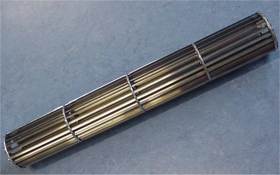
This picture shows the finished blower wheel. It highlights the multiple support rings along the shaft. Finally, engineers can see how it resists bending.
Longwell Engineering Specification LWMI-45×310-03: This approved factory file shows the final design. It defines the tight riveting tolerances. Meanwhile, quality teams use it during dynamic balancing.
How to Specify High-Aspect-Ratio Blower Wheels
Missing small details will delay a new metal cross flow impeller project. You must define the physical limits early. This ensures you get a useful quote quickly.
- Count the support rings: First, do not just measure the total length. You must count the support plates on your sample. These plates dictate how the wheel handles stress.
- Define the unbalance limit: Next, state your unbalance limit based on length. For wheels under 500 mm, demand a target under 200 mg. In short, this is a solid mechanical rule.
- Check the shaft ends: Radial runout at the shaft connection causes problems. If the metal wobbles by more than 0.10 mm, trouble starts. Consequently, the motor bearings will fail early.
- Provide exact tolerances: Finally, send your supplier a recognized tolerance standard. We can handle custom NPI in 90 days. So, giving us a standard like GB/T 1804-V speeds up pricing.
Related: Cross Flow Fans.
Technical Documentation & Resources
Browse our cross-flow fans range, the AC cross-flow fans section, or cross-flow impellers.
Have a Similar Fan Requirement?
Longwell’s engineering team delivers custom spec sheets and samples within 90 days. Since 1990, we have supplied EC fans and blowers to OEMs across HVAC, cold chain, data center, and industrial applications worldwide.
Browse Related Products:
🏆 ISO 9001 / ISO 14001 / ISO 45001 | CE (TÜV) | UL/ETL | ATEX Zone 21/22 | AMCA 210-16 / ISO 5801 tested
Choose the right cross flow fan
Longwell manufactures 495 cross flow fans in-house. Send airflow, static pressure and voltage — an engineer replies with a matching model, performance curve and price within one working day.