An IP upgrade with a wiring clause
An OEM cooling high-density electrical components needed a 310 VDC axial fan upgraded from a catalog model. Notably, their wiring clause was absolute: an integrated fan terminal block, no flying leads.
However, the reference model offered IP42 and a galvanized steel impeller. Their environment demanded more on both counts.
The full requirement
- First, 2600 m3/h target airflow in suction configuration, pulling air over the motor.
- Next, IP55 against dust and low-pressure water jets, inside 380 by 380 by 110mm.
- Meanwhile cold starts at -25C and continuous duty at 60C, under 70 dB(A).
- Finally, first-article samples inside the month, 1,000 units a year, CE marked, verified to ISO 5801.
Why the wiring method got its own clause
Simply put, these fans get wired in the field, into equipment assembled elsewhere. A flying lead is a factory-friendly part and a field-hostile one. Someone must cut it to length, strip it, terminate it and route it, whoever stands there that day.
By contrast, a fan terminal block moves all of that judgment into the fan design, once, instead of repeating it a thousand times a year in the field.
What the terminal block changes
The project had three changes to carry at once: the ingress rating, the impeller material and the connection method. In practice, they interlock more than they look.
The impeller change
Firstly, we rejected the catalog galvanized steel impeller early. Surviving IP55 water exposure would demand heavy coating, and coatings on a spinning part are a wear item.
Instead, a PA6 glass-fiber impeller carries the rating in the material itself, sheds weight, and starts happily at -25C within this design speed range. So the material does the job the coating would have merely promised.
What the fan terminal block actually buys
Repeatability, first of all. Every one of the thousand units presents the same terminals in the same place with the same torque figure, so field wiring becomes a procedure instead of a craft.
Serviceability, second. With a fan terminal block, a field swap means unscrewing conductors and rescrewing them, minutes with a screwdriver, instead of cutting spliced leads and re-terminating in a live cabinet.
Sealing, third. On an IP55 product the wiring entry is part of the rating. A block designed into the housing seals as a feature, while a lead exit relies on a grommet surviving field handling.
The 310 VDC context
Here the customer rectifies centrally and distributes DC, so the fan EC electronics ride a 310 VDC bus directly. At that voltage, secure and inspectable terminations are not a comfort preference. After all, loose strands and stressed splices are how DC arc faults begin.
The schedule
Finally, first articles were due within the month, which the platform approach made possible. The changes are an impeller material, a sealing level and a connection interface on an existing 300mm frame, not a new fan. Verification follows ISO 5801 methods.
Technical Specifications
The connection row is easy to skim past. On a thousand field-wired units it decides more service outcomes than the airflow row.
| Parameter | Value |
|---|---|
| Airflow (Max) | 2523 m³/h (1484 CFM) |
| Static Pressure (Max) | 216 Pa |
| Nominal Voltage | 310 VDC |
| Voltage Range | 248 ~ 372 VDC |
| Speed | 2050 RPM |
| Current | 0.5 A |
| Power Input | 150 W |
| Noise Level | 68 dB(A) |
| Operating Temperature | -25°C to +60°C |
| Protection Type | IP55 |
| Insulation Class | Class B |
| Dimensions | 380 x 380 x 109 mm (Impeller Ø 300mm) |
| Certifications | CE, RoHS, REACH |
Technical Documentation
LWAD3G300ZS-5PKW-07-00 Final Specification PDF
Meanwhile the document contains the approved parameters for the IP55 custom build, vital for the OEM engineering team finalizing their electrical integration and thermal load calculations.
Mechanical integrators require this drawing to design the mounting chassis and confirm the 109mm depth clearance around the suction-side motor block.
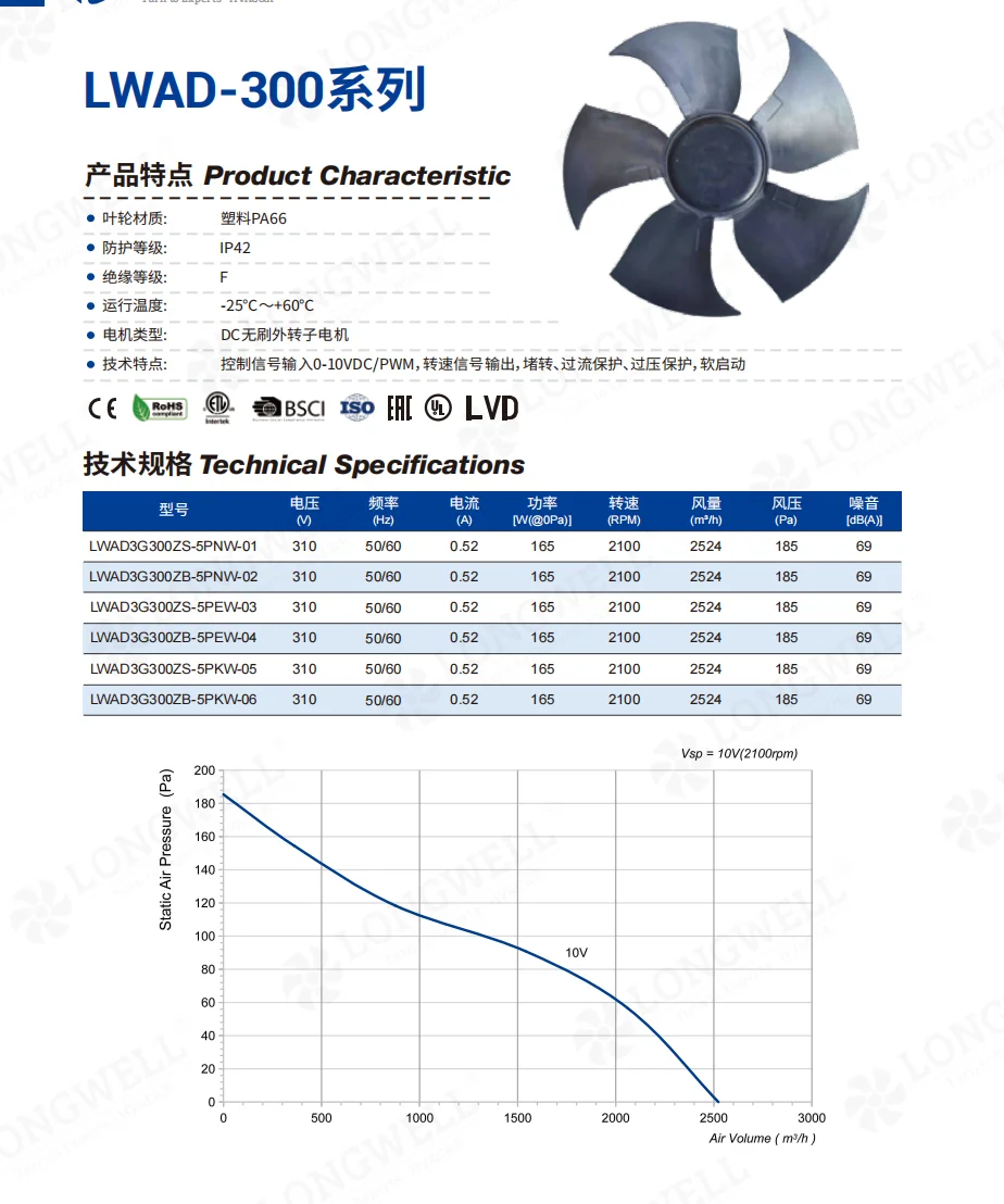
LWAD3G300ZS-5PKW-05 Baseline Specification PDF
Here the reference file shows the original IP42 steel-impeller configuration, providing a direct comparison to highlight the subsequent IP55 design modifications.
Choosing your connection method
The connection method deserves a deliberate choice on any field-wired fleet. In the end, four questions settle it.
- Count who terminates, and where. After all, factory-built assemblies tolerate flying leads because one trained line does the work. Field wiring by many hands is the case for a fan terminal block, and the larger the fleet, the stronger the case.
- Check the block against the ingress rating. After all, a terminal block is a hole in the housing unless it is designed as part of the sealing. Hence, confirm the IP rating applies to the fan as wired, with the stated cable and gland, not to the housing alone.
- Match the block to the voltage class. Terminal spacing, creepage and wire capacity must suit the bus. Moreover, a 310 VDC system is less forgiving of casual terminations than mains AC. State the conductor sizes you will actually bring.
- Write the torque on the drawing. Indeed, screw terminals loosen when under-tightened and deform when over-tightened, and field torque varies wildly by wrist. A stated value with a re-check interval turns the connection into a maintainable item.
See our axial fans range, the DC axial fans section, or EC axial fans.
Questions about fan wiring methods
When are flying leads actually the better choice?
In factory-built assemblies where one production line terminates every unit into a known harness. There the lead saves a connector cost, and the process controls the quality. However, the calculation flips as soon as wiring moves into the field or across many installers.
Does a terminal block hurt the IP rating?
Only if it is an afterthought. Properly designed into the housing with the right gland and gasket, a fan terminal block is part of how the rating is achieved. The question to ask is whether the IP certificate covers the fan in its wired condition.
Why do DC systems care more about termination quality?
Because DC arcs do not put themselves out the way AC arcs do at each zero crossing. A loose strand or a failing splice on a 310 VDC bus can sustain an arc that AC would quench, which is why inspectable, torqued terminations earn their place on DC fleets.
What should the drawing say about the connection?
Namely: the terminal layout and labels, the accepted conductor sizes, the tightening torque, and the cable gland that preserves the IP rating. With those four on the controlled drawing, a thousand field installations follow one written standard.
Technical Documentation & Resources
Need the same thing for your own unit?
Give us the numbers and the envelope, and you get a shortlist rather than a catalog. Meanwhile custom spec sheets and samples run to 90 days. Since 1990 Longwell has supplied EC fans and blowers to OEMs in HVAC, cold chain, data center and industrial markets.
Browse Related Products:
🏆 ISO 9001 / ISO 14001 / ISO 45001 | CE (TÜV) | UL/ETL | ATEX Zone 21/22 | AMCA 210/211 / ISO 5801 tested
Choose the right axial fan
Longwell manufactures 1,086 axial fans in-house. Send airflow, static pressure and voltage — an engineer replies with a matching model, performance curve and price within one working day.