Sizing an Electronics Enclosure Cooling Fan
The customer needed a reliable electronics enclosure cooling fan for a small outdoor box. First, the power rail set the rules. The system supplied only 24V. Next, the space for the fan was very tight. The fan housing could not exceed 65 mm in height or depth. Meanwhile, the total length had to stay under 475 mm. Also, the unit had to run outdoors. This meant handling a harsh temperature span from -25C to +60C. Consequently, normal indoor commercial blowers failed this test immediately. We needed a better industrial option.
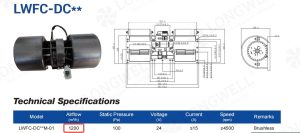
Instead, the customer looked at our 40420MN-07 model. As an electronics enclosure cooling fan, this catalog unit fits the space well. However, that rating gives only 146 m3/h. This electronics enclosure cooling fan had to do more. The customer needed much more cooling air. Their thermal load calculation required an exact air volume of 191 m3/h. Furthermore, the fan sits right next to a daily access panel. So, a bare spinning impeller created an obvious safety risk for maintenance workers. The engineers had to add a metal safety grid.
In short, the main engineering challenge was very clear. We had to supply a modified electronics enclosure cooling fan inside a strict 470 mm footprint. We also had to add a protective safety guard. Finally, the team needed to hit 191 m3/h of airflow. We had to achieve all this without exceeding a strict 0.17A current limit. We test all such performance metrics strictly to AMCA 210-16 methods.
Engineering a High-Airflow Modified Unit
First, we looked at different motor types to hit the 191 m3/h target. For instance, an AC shaded pole motor easily moves huge air volumes. Many engineers choose AC motors for simple projects. However, the system only offered DC power from the main board. We rejected AC motors entirely because adding a separate power inverter was too costly. Next, we considered making the aluminum impeller much longer. A longer fan wheel naturally pushes more air without altering the motor speed. Even so, the 470 mm total length limit stopped us cold. A longer housing simply would not fit in the metal enclosure. Therefore, a custom DC cross flow fan remained the only real choice.
Choosing the Right Motor and Grid
Consequently, we focused on tuning the exact internal components. We kept the optimized 420 mm aluminum impeller. Then, we paired it directly with a 3-phase BLDC motor. The safety rule meant we had to add an iron grid over the outlet. This strict change updated the part name from “MN” to “MG”. The “G” suffix stands for the iron safety grid. Naturally, putting a thick metal grid in the air path creates a new problem. The grid blocks the air flow and causes extra turbulence. So, pushing 191 m3/h through this strict barrier required careful motor tuning. We adjusted the copper windings to boost the starting torque.
Managing Power and Noise Trade-Offs
Furthermore, we used a standard 0-10V speed control signal. This specific setup guarantees the fan runs perfectly at its 2400 RPM rated speed. Meanwhile, we altered the internal motor design to keep input power exactly at 4W. Every engineering choice has a clear price attached to it. Here, the cost of this safety change was extra aerodynamic noise. The iron safety grid creates significant wind drag. This drag makes the fan noticeably louder than the bare impeller version. By contrast, the strict thermal budget meant we could not accept a larger, hotter motor. Finally, the chosen LWCD-43420MG-07 design fit the 63.5 mm by 60 mm space exactly. It delivered the exact airflow and finger safety the low-voltage enclosure required.
Technical Specifications
| Air Volume | 191 m3/h |
| Speed | 2400 r/min |
| Input Power | 4 W |
| Voltage | 24V DC |
| Current | 0.17 A |
| Dimensions (Overall Length) | 470±2 mm |
| Impeller Length | 420 mm |
| Housing Cross-Section | 63.5 mm x 60 mm |
| Operating Temperature | -25 C to +60 C |
| Housing Material | Iron |
| Impeller Material | Aluminum (Al) |
| Speed Control | 0~10V |
| Insulation Class | B |
| Bearings | Ball bearing |
These fourteen parameters define the exact operational limits of the final electronics enclosure cooling fan design. Consequently, the input power and air volume rows matter most for this project. The system must move large amounts of air without drawing excessive current. Therefore, achieving 191 m3/h on just 4W of power keeps the main thermal budget perfectly safe. This high efficiency relies entirely on the tuned 3-phase BLDC motor.
Reference: AMCA 210 covers the test method behind these figures.
Technical Documentation
 First, this image shows the catalog baseline for the 40420MN-07 model. The table clearly lists the standard 146 m3/h limit before our engineering modifications.
Download LWCD-43420MG-07-00 Drawing (PDF)Second, this finalized CAD PDF provides the exact mounting hole coordinates for the enclosure. It also details the wire definitions and the upgraded 191 m3/h performance parameters.
How to Specify a Modified Cooling Module
First, standard catalog fans often fail to meet exact physical limits. You will likely face this same cooling issue in tight electronics enclosures. Therefore, when you specify a DC cross flow fan, consider these practical rules.
- Measure hard physical limits first: Measure your absolute maximum space before you ask for more air. For example, the strict 470 mm length limit here stopped us from using a longer fan. Always check your enclosure depth.
- Account for any safety guards: Next, check if the fan blows air into a user area. Adding an iron grid changes the static pressure curve. A fan rated for 150 m3/h drops in airflow when you add a metal guard.
- Confirm all control signals: Meanwhile, verify exactly what signal your board sends. State clearly if you use a 0-10V signal or a simple PWM signal. This step prevents nasty motor control errors later during final assembly.
- State your absolute current ceiling: Finally, always give the maximum current your supply can safely handle. We shape the aluminum impeller to fit your strict 0.17A limit. This careful balance keeps your main rail voltage completely steady.
In short, clear measurement limits yield a highly useful first quote. Related: Cross Flow Fans.
Engineering Questions on Cross Flow Designs
Technical Documentation & Resources
Browse our axial fans range, the AC axial fans section, or EC axial fans.
Have a Similar Fan Requirement?
Longwell’s engineering team delivers custom spec sheets and samples within 90 days. Since 1990, we have supplied EC fans and blowers to OEMs across HVAC, cold chain, data center, and industrial applications worldwide.
Browse Related Products:
🏆 ISO 9001 / ISO 14001 / ISO 45001 | CE (TÜV) | UL/ETL | ATEX Zone 21/22 | AMCA 210-16 / ISO 5801 tested
Choose the right cross flow fan
Longwell manufactures 495 cross flow fans in-house. Send airflow, static pressure and voltage — an engineer replies with a matching model, performance curve and price within one working day.