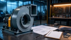
Blower wheel removal is a geometry and load-path problem before it is a pulling problem. A wheel that slides off its shaft may need little force; a seized hub may require a controlled extraction plan. In either case, the first decision is to identify the actual hub connection and preserve the wheel’s installed position. The equipment and wheel manufacturer’s instructions determine the permitted tools, fastener sequence, limits and reassembly checks.
This guide is a field decision aid for qualified service personnel. It illustrates why force should reach the hub on an approved assembly and when to stop. It is not a model-specific removal procedure, torque schedule or assurance that a wheel can be reused.
Control hazardous energy; identify the hub, shaft and every retainer; record the axial datum and clearances; then use only an extraction method approved for that exact assembly. Stop if the wheel, shaft or tooling moves in an unexpected way. Refit and test against the recorded geometry and the manufacturer’s criteria.
Identify the hub before choosing a tool
A set screw, key, collar or taper bushing changes the release sequence. Looking only at the visible screw can miss another retainer on the rear face or a different hub style. Find the product label or drawing and inspect the full hub circumference, shaft end, support and housing. Record the wheel material and any balance weights or clips. Do not remove a balance feature to make a puller fit.
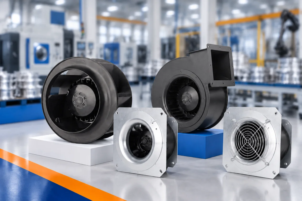
LONGWELL’s forward-curved centrifugal fan family illustrates one relevant family of housed wheels, but the family page does not identify the hub design or service method of the unit in front of you. For that, use the exact assembly drawing and service instructions.
Record the installed geometry before the wheel moves
Photograph the shaft projection, wheel orientation, inlet overlap, housing clearance, fastener locations and any balance marks. Marking a single shaft line can help, but a service record should also include a measurable axial datum. A previous installation may already be wrong, so compare the recorded position with the exact drawing where one exists. Document any rub marks before disassembly; they may reveal an existing alignment problem rather than damage caused by removal.
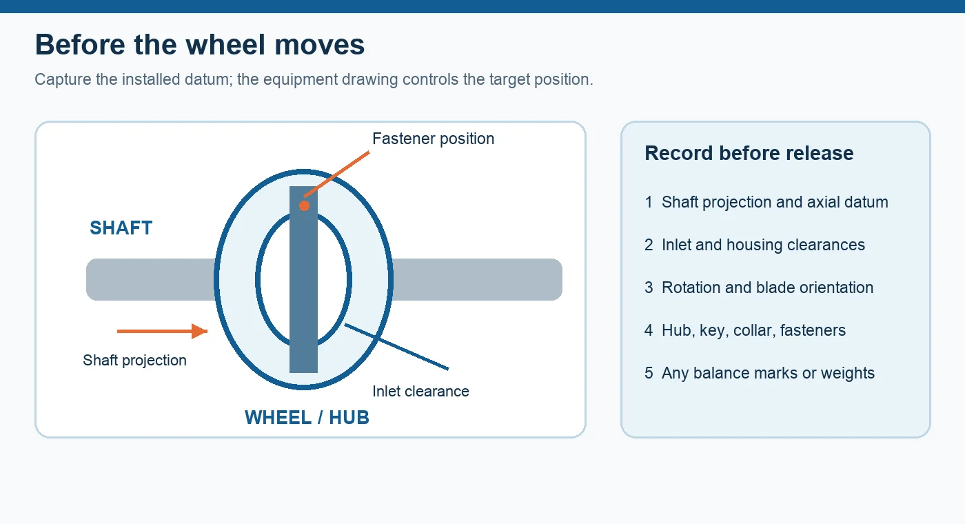
The first diagram separates the measurements from the generic wheel sketch. It does not specify a clearance value. The acceptable position and gap depend on the particular wheel, inlet and housing.
Control energy and create access
Unexpected startup, stored rotation, electrical energy and other site-specific sources must be controlled before guards or access panels are opened. Follow the site’s hazardous-energy procedure and the equipment instructions. The applicable OSHA control-of-hazardous-energy standard describes the general industry boundary in the United States; local requirements and the exact equipment procedure still govern the job. A qualified person should decide whether the complete blower assembly needs to be supported or removed to obtain straight access to the hub.
Do not brace a lever against thin housing metal or carry the wheel’s weight through its blades. Provide enough access to see both the tool contact points and the shaft axis throughout the pull.
Release retainers and prepare the shaft
Check for hidden screws, keys, collars, taper-bushing bolts and shaft-end damage. A screw that remains partly engaged can behave like a seized hub. A burr on the shaft can also catch the bore as the hub moves outward. The exact instructions determine whether a fastener should be removed, loosened in a sequence or used in a release hole. There is no universal set-screw or bushing sequence.
Clean the exposed shaft without removing material that the fit depends on. Penetrant, heating or cutting are not default remedies: material, motor seals, electrical components, coatings and the equipment manual can rule them out. If the approved method is unclear, pause for the manufacturer’s service guidance rather than increasing force.
Keep the extraction load on the approved hub points
Where the exact wheel and motor instructions permit a puller, align its spindle with the shaft axis and place symmetrical jaws or fixtures only at approved hub surfaces. The load should move the hub along the shaft, not dish a side plate, bend a blade or push the motor shaft into its bearings. Protect the shaft end as specified by the tool and motor instructions. A generic two- or three-jaw puller is not suitable for every hub.
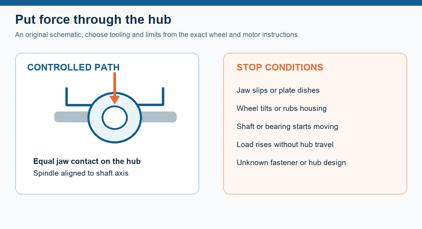
The second diagram shows the intended force path and the conditions that require a stop. If a jaw slips, a plate deforms, the wheel tilts, the shaft moves with the hub or load rises without travel, release the tool and reassess the remaining restraint or the method. More force is not a diagnosis.
Inspect and reassemble against the same datum
Once removed, inspect the bore, key or bushing, shaft contact surface, blades, side plates, welds and balance features. Damage can make the wheel unsuitable for reuse even when it still turns. Cleaning should preserve balance weights and avoid bending blades. Refit the wheel using the exact fastener and torque instructions; restore the specified axial position and check the recorded inlet and housing clearances around the full rotation.
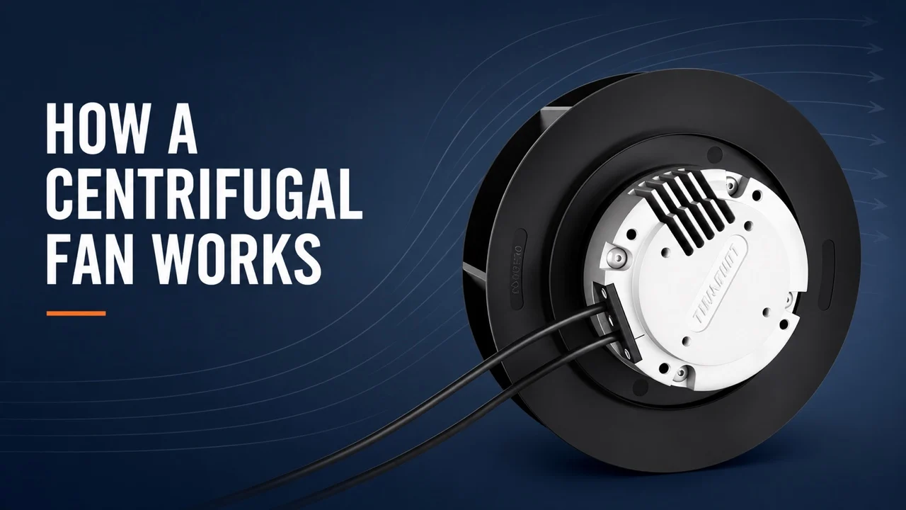
With guards restored and the site procedure complete, compare rotation, current, vibration, noise and delivered airflow with the unit’s own baseline or acceptance criteria under comparable operating conditions. An absence of rubbing during hand rotation is necessary but does not by itself prove installed duty. For a broader explanation of wheel and housing roles, see how a centrifugal fan works.
What to send for an engineering review
When the hub style or replacement identity remains uncertain, provide the equipment and wheel nameplates, photos of both hub faces, shaft and bore dimensions, rotation, housing and inlet views, the existing drawing or manual revision, and the duty point. Those details let an engineer compare the actual assembly rather than guessing from a wheel diameter or a family photo. LONGWELL can review a relevant fan or wheel family against that evidence; a product page alone does not confirm an exact replacement or compatibility.
Choose the right fan impeller
Longwell manufactures 10 fan impellers in-house. Send airflow, static pressure and voltage — an engineer replies with a matching model, performance curve and price within one working day.