A fan can have a wire grille and still leave a rotating part accessible from another direction. Guard selection therefore starts with the installed machine, not a catalogue photograph or a mesh size chosen in isolation. The useful question is: which access routes remain during operation, cleaning and maintenance, and what prevents contact along each route?
This guide helps equipment engineers structure that review. It does not supply universal guard dimensions or declare an installation compliant; the applicable requirements and equipment-specific assessment determine acceptance.
Map access to the whole rotating assembly
Trace access at the inlet and outlet, then look beyond the wheel. A shaft, coupling, belt drive or motor area may need its own assessment. Include the approaches created by adjacent panels and service openings, rather than checking only the side normally visible to an operator.
Separate normal operation from cleaning and maintenance. Record which parts become accessible when each relevant cover is opened or removed. This makes an incomplete review easier to spot: an inlet grille cannot answer a question about an exposed coupling or an unprotected outlet.
Read the product image as a component, not a safety verdict
The Longwell component image below shows black axial blades, mounting ears and a wire grille behind the blades. The blade side facing the viewer remains exposed in this photograph. That observation does not establish the guarding of a finished machine; it shows why a rear grille alone cannot demonstrate protection from every direction.
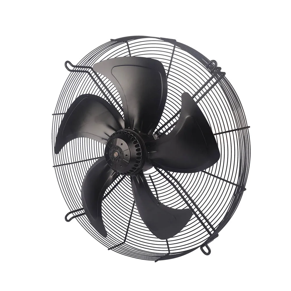
The AC axial fan range is a family-level starting point for component research, not identification of this exact pictured model. A candidate still needs to be assessed with its intended enclosure, mounting arrangement and accessible surroundings.
Evaluate opening geometry and distance together
Opening shape, opening size and distance to the hazardous part belong in the same review. Recording only a nominal mesh size leaves the geometry incomplete. Establish which access condition is being assessed and use the applicable requirements to evaluate that combination.
Also examine the guard perimeter and mounting interface. A panel may look closely spaced across its centre while leaving a different access route around an edge. Do not convert a photo, a generic drawing or another machine’s guard dimensions into an acceptance rule for the current installation.
Use a guard selection and inspection record
A useful record states what was checked and what remains unresolved. The following table keeps selection decisions and later inspections tied to the same physical features.
| Review item | Evidence to record | Reason to reopen the assessment |
|---|---|---|
| Access routes | Inlet, outlet and other reachable rotating parts, for each relevant task. | A changed panel, service opening or installation creates another approach. |
| Openings and distance | Opening geometry and its relationship to the hazardous part. | Fit or deformation changes the assessed arrangement. |
| Structure and attachment | Guard rigidity, mounting points, fasteners and observed condition. | Damage, corrosion, looseness or missing attachments undermine the arrangement. |
| Access-control function | Fixed or interlocked design and the required validation evidence. | Bypass, alteration or an unresolved function check. |
| Airflow and servicing | Installed airflow conditions, fouling and the planned cleaning access. | A change affects airflow or makes routine servicing inconsistent with the assessed method. |
Check rigidity, attachment and interlocked functions
A guard must retain the arrangement being assessed. Review its strength and rigidity together with the supporting structure and fasteners. Look for deformation that could change access or bring the guard towards a rotating part. A guard’s presence is not evidence that these checks have passed.
For an interlocked guard, identify the intended safety function and obtain the necessary validation for the actual arrangement. An interlock is not interchangeable with a fixed barrier, and neither should be accepted simply because a similar component appears on another machine.
Keep stopping separate from hazardous-energy control
A stop command or an interlock response does not by itself establish isolation for maintenance. The review must address stored energy, coast-down and possible windmilling, along with the equipment’s prescribed hazardous-energy control procedure.
Qualified personnel should establish and verify the required safe state before access. Do not use a general waiting period or a quick observation of the blades as a substitute for that procedure. Inspection planning should make this boundary clear, especially where cleaning requires guard removal.
Verify airflow with the guard fitted, then maintain the arrangement
A guard also affects the air path. Include its pressure loss, possible noise effects and fouling in the installed-system review. The guide to fan performance curves provides background on relating fan performance to system conditions; it does not establish a guard’s safety or quantify losses for this axial component.
Retain the accepted guard configuration in the equipment record. Subsequent inspections should check fit, damage, corrosion, attachments and evidence of bypass. If the arrangement changes, revisit the affected access routes and functions rather than carrying forward an earlier acceptance unchanged. For a component enquiry, prepare the fan identification, installation views, access requirements and operating conditions so that the discussion concerns the actual assembly.