Engineering a 780mm plastic impeller for 24V DC
The customer needed a custom
780mm plastic impeller. First, they paired it with a 24V DC motor. They had strict space limits for their unit. Therefore, they asked for four specific sizes. These were 81mm, 95mm, 101.5mm, and 105mm. Meanwhile, all four sizes needed the exact same 780mm length. This let them fit into older brackets. Next, the unit needed precise speed control. Consequently, the motor had to accept 0-10V and PWM signals.
A long 780mm span bends easily. So, we had to hold strict physical limits. This stops bad vibration. Instead of standard rules, the radial runout had to stay under 0.7 mm. First, the axial runout could not pass 0.6 mm. Next, the steel shaft limit was exactly 0.2 mm. Finally, this unit must meet IEC 60335 for safety. Therefore, the motor parts stay fully separate from the air.
Choosing the rotor material and building the fan
We tested a few materials for the main rotor body. First, we rejected solid metal. Metal adds too much mass for a 50 W motor. Consequently, a heavy rotor wears out the bearings faster. This drops the total lifespan. Instead, we picked AS+GF30%. This is plastic reinforced with 30% glass fiber. Therefore, this blend gives the stiffness needed for a long span. However, the hard glass wears down our molds faster. This drives up the unit cost.
Next, we looked at how to build the fan. By contrast, glue breaks down over time from vibration. So, we rejected glued joints. Instead, we chose ultrasonic welding. First, this melts the plastic to make a solid bond. Consequently, the finished part has no cracks or loose parts. Even so, we tested the welded rotor up to 1600 RPM. This proved it runs quietly at top speeds.
Balancing the rotating span
A long rotor acts like a flexible shaft. Therefore, dynamic balancing was our biggest test. First, we set a strict mechanical balancing rule. Consequently, we allowed only up to three balancing clips per unit. By contrast, using more clips hides bad molding. Next, we kept the final unbalance under 0.3g. We tested this at 1200 RPM. Furthermore, we held the axial runout safely under 0.6 mm. Meanwhile, the steel shaft runout stayed under 0.2 mm. Finally, these tight limits protect the motor bearings.
Integrating the 24V DC motor
We built two DC external rotor motors for this job. These are the LWDM72-023 and LWDM92-010 models. First, we put our SmartEC control logic inside. Consequently, users can swap between 0-10V and PWM control easily. Furthermore, the motors hit a rated speed of 1000 RPM. Meanwhile, the IP42 rating blocks dust and water drips. Finally, Class B insulation keeps the copper windings safe from heat.
Technical Specifications
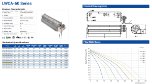
| Component | Cross Flow Rotor with External Rotor Motor |
| Impeller Diameters | 81mm, 95mm, 101.5mm, 105mm |
| Impeller Length | 780mm |
| Material | AS+GF30% (Black) |
| Operating Voltage | 24V DC |
| Input Power | 50 W |
| Rated Current | 2.2 A |
| Rated Speed | 1000 RPM |
| Control Input | 0-10V / PWM |
| IP Class | IP42 |
| Insulation Class | Class B |
| Steel Shaft Dimensions | 8mm diameter, 30mm length |
| Runout Limits | Radial < 0.7 mm, Axial < 0.6 mm, Shaft < 0.2 mm |
| Balancing Target | < 0.3g at 1200 RPM (Max 3 clips) |
These numbers set the limits of the final unit. First, the glass-filled plastic sets the weight. Furthermore, the tight runout limits keep the long span smooth. Finally, the IP42 rating proves the motor stops dust.
Reference: ISO 21940 covers the test method behind these figures.
Technical Documentation
Impeller Engineering Drawing (101.5mm). First, this main drawing shows the exact weld details and length limit.
Impeller Engineering Drawing (81mm). Next, this file lists the strict balancing rules for the narrow model.
DC Motor Specification Sheet. Finally, engineers need this sheet to wire the control inputs safely.

Specifying Long Rotors for DC Systems
If your project needs a long span like this
780mm plastic impeller, you must define your limits clearly.
- First, write your runout rules clearly on your drawings. Furthermore, a radial runout over 1.0 mm causes bad vibration. So, aim for strictly under 0.7 mm.
- Next, pick a stiff material like glass-filled AS. Consequently, this choice stops the rotor from sagging and rubbing against the housing.
- Instead of allowing endless balancing clips, limit them to three pieces. Therefore, you force the factory to maintain better molding quality.
Related: Cross Flow Fans.
Frequently Asked Questions
Technical Documentation & Resources
- Technical documentation 1 (PDF)
- Specification sheet 2 (PDF)
- Specification sheet 3 (PDF)
- Technical documentation 4 (PDF)
- Technical documentation 5 (PDF)
- Technical documentation 6 (PDF)
- Specification sheet 7 (PDF)
- Technical documentation 8 (PDF)
- Technical documentation 9 (PDF)
- Specification sheet 10 (PDF)

Browse our axial fans range, the AC axial fans section, or EC axial fans.
Have a Similar Fan Requirement?
Longwell’s engineering team delivers custom spec sheets and samples within 90 days. Since 1990, we have supplied EC fans and blowers to OEMs across HVAC, cold chain, data center, and industrial applications worldwide.
Browse Related Products:
🏆 ISO 9001 / ISO 14001 / ISO 45001 | CE (TÜV) | UL/ETL | ATEX Zone 21/22 | AMCA 210-16 / ISO 5801 tested
Choose the right fan impeller
Longwell manufactures 10 fan impellers in-house. Send airflow, static pressure and voltage — an engineer replies with a matching model, performance curve and price within one working day.