Space Constraints for a Compact Electronic Enclosure
Finding the right 60mm dc cooling fan requires strict attention to voltage limits. It also demands exact physical dimensions. First, the customer submitted a requirement for a square frame blower. They needed this unit to cool electronics on a 24VDC power bus.
Next, space constraints strictly limited the physical envelope to exactly 60x60x25mm. Therefore, the fan had to fit tightly into the chassis. It could not restrict intake air. It could not cause mechanical interference.
Furthermore, the application demanded a specific airflow. The heat load required an airflow approaching 17 CFM. However, the noise ceiling remained tight at roughly 30 dB(A). Meanwhile, operating temperatures ranged from -10°C to +60°C.
This wide temperature window told us a specific fact. The equipment likely faces mild outdoor conditions or unconditioned indoor environments. Also, the original request specified an AWG28 wire for the 300mm power lead. Yet, mechanical routing in long cable runs places physical stress on very thin wires.
This problem happens often during factory assembly. Finally, the customer required UL Class A insulation. They needed standard safety protections against locked rotor conditions. Therefore, any proposed design had to meet strict appliance safety standards.
Component Selection and Engineering Trade-Offs
Addressing this specification meant balancing several factors. We had to weigh rotational speed, noise, and bearing life. First, we evaluated multiple approaches. We needed to meet the thermal load strictly inside the 60x60x25mm frame limit. Every choice carried a specific consequence for the final product lifespan.
Mapping the 60mm dc cooling fan Profile
First, we mapped the required 16.87 CFM for this 60mm dc cooling fan against the physical constraints. Pushing this volume of air through a small diameter requires higher rotational speed. Consequently, we set the nominal speed to 3600 RPM. The fan achieves 16.87 CFM at zero static pressure under these conditions. However, the strict trade-off here is acoustic. At 3600 RPM, the noise level reaches 30.41 dB(A). We could have lowered the speed to 3000 RPM. That change would reduce the ambient noise noticeably. Instead, we kept the higher speed. A slower fan drops airflow well below the thermal safety margin. The customer’s heat sinks strictly required that exact volume.
Bearing Selection for Thermal Extremes
Next, we considered standard sleeve bearings. Sleeve bearings cost less to produce. They also run slightly quieter at low rotational speeds. However, we rejected them entirely. The standard lubricant degrades quickly at 60°C. Also, sleeve bearings perform poorly if the customer mounts the equipment vertically. Instead, we selected a two-ball bearing system. This choice ensures a 50,000-hour life expectancy at 25°C. The ball bearing assembly adds a minor cost premium. It also creates a slight mechanical hum. Even so, it prevents premature rotor failure in the field.
Electrical and Material Upgrades
Finally, we addressed the motor protection and wiring gauge. The initial request asked for AWG28 wire. However, a 300mm lead wire requires physical strength during installation. So, we upgraded the specification to UL1007 24AWG. This thicker wire easily handles the 0.06A current. It also prevents breakage when technicians pull cables through tight chassis routes. Furthermore, we applied impedance protection for the motor. This specific design protects the motor from catching fire. It works flawlessly even if the rotor locks completely for 72 hours at 24VDC. The frame and impeller consist of PBT plastic. This material is strictly rated to UL94V-0 standards. In short, the final configuration safely delivers the required cooling within the rigid electrical limits.
Technical Specifications
| Parameter | Value |
|---|---|
| Rated Voltage | 24.0 VDC |
| Operation Voltage | 12.0-26.5 VDC |
| Input Current | 0.06 A |
| Input Power | 1.44 W |
| Rated Speed | 3600 RPM (±10%) |
| Maximum Air Flow (at 0 Static Pressure) | 16.87 CFM |
| Maximum Air Pressure (at 0 Air Flow) | 3.02 mm H2O |
| Acoustical Noise (AVG.) | 30.41 dBA |
| Insulation Type | UL: CLASS A |
| Insulation Strength | 10 Meg OHM MIN. At 500VDC |
| Dielectric Strength | 5 mA Max, at 500VAC~80Hz, 1 Minute |
| Life Expectancy | 50,000 Hours continuous operation at 25°C with 15~65%RH |
| Operating Temperature | -10°C ~ +60°C |
| Lead Wire | UL1007 24AWG, Length: 300+/-10mm |
| Frame & Impeller Material | PBT Plastic UL:94V-0 |
| Bearing Type | Two Ball Bearings |
First, the 1.44W input power ensures a minimal parasitic load on the main 24V power supply. Next, the 50,000-hour life expectancy directly validates the dual ball bearing choice.
Reference: AMCA 210 covers the test method behind these figures.
Technical Documentation

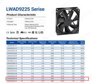
This image displays the compact plastic frame and standard mounting hole layout. Engineers need this visual to plan direct chassis integration.
LWAD6025MM-11-00 Technical Specification Document
Engineers will use this full document to verify the locked rotor protection mechanisms. It also confirms the exact wiring pinouts and material safety ratings.
Guidelines for Specifying Compact Enclosure Blowers
When you face rigid thermal limits in small electronic enclosures, exact specifications prevent costly redesigns. Therefore, you should verify these exact parameters before locking in a physical footprint.
- First, measure the internal ambient temperature. Do not just measure the external room temperature. Components inside a sealed box easily heat the local air up to 60°C. This change immediately alters the bearing life expectations.
- Next, calculate the static pressure drop across your vents. The specified 60mm dc cooling fan moves 16.87 CFM at zero pressure. However, it stalls completely at 3.02 mm H2O.
- Furthermore, review wire gauge requirements for long cable runs. Upgrading from AWG28 to AWG24 adds essential mechanical strength. This strength prevents broken wires during factory assembly.
Related: Axial Fans.
Frequently Asked Questions
Technical Documentation & Resources
Browse our axial fans range, the AC axial fans section, or EC axial fans.
Have a Similar Fan Requirement?
Longwell’s engineering team delivers custom spec sheets and samples within 90 days. Since 1990, we have supplied EC fans and blowers to OEMs across HVAC, cold chain, data center, and industrial applications worldwide.
Browse Related Products:
🏆 ISO 9001 / ISO 14001 / ISO 45001 | CE (TÜV) | UL/ETL | ATEX Zone 21/22 | AMCA 210-16 / ISO 5801 tested
Choose the right dc cooling fan
Longwell manufactures 38 dc cooling fans in-house. Send airflow, static pressure and voltage — an engineer replies with a matching model, performance curve and price within one working day.