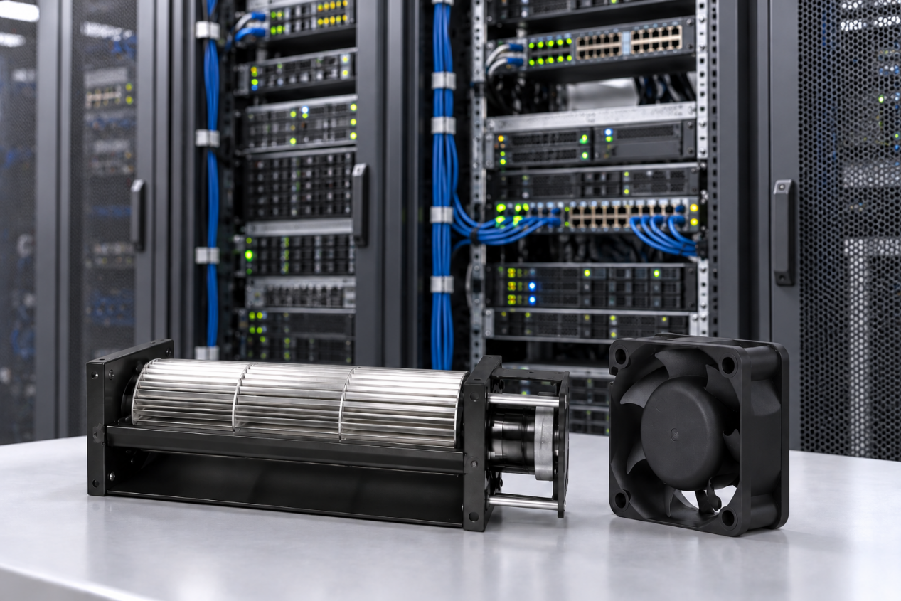
As industry transitions towards electrification, automation, and digitalization, electronic devices are playing an increasingly significant role in various fields. As operating temperature rises, excess heat can negatively affect components’ performance, reliability, and even the service life. At the same time, electronic components and enclosures become increasingly compact, and thermal management becomes important for optimal performance and product lifespan.
This article explains the main cooling methods for electronic equipment, common thermal and airflow challenges, and practical best practices for selecting and applying cooling fans in different electronic systems.
Why is Cooling Important for Electronic Equipment?
Heat is unavoidable in electronic equipment. Motors, processors, power supplies, and batteries all release part of their input energy as heat during operation.
The problem starts when heat remains inside the enclosure. Internal temperature rises, components run hotter, and reliability gradually declines. In high-load equipment, overheating may also trigger protection functions or cause unexpected shutdowns.
Therefore, cooling is part of the equipment design, not an optional addition. Its job is to remove the heat produced during operation and prevent excessive temperature buildup.
Cooling Methods for Electronic Equipment
Active Cooling Methods
Active cooling uses powered components to remove heat from equipment. For many electronic devices, using a cooling fan is the simplest solution. It moves air through the enclosure and carries heat away from components. But fan selection should not be based on airflow rating alone. Filters, heat sinks, grilles, and restricted passages all reduce the airflow available inside the actual equipment.
However, fan performance cannot be considered separately from the airflow path. The positions of the air inlet, outlet, and major heat sources also affect how effectively air can move through the enclosure and remove heat. The selected cooling fan should match the actual operating conditions inside the equipment.
Passive Cooling Methods
Passive cooling works without fans or other powered airflow. Instead, heat moves through the component, PCB, heat sink, or enclosure and is released to the surrounding air. This approach is usually enough for equipment with relatively low heat output. Heat sinks are often added where more surface area is needed for heat dissipation. Thermal interface materials and PCB thermal vias can also help move heat away from local hot spots.
Challenges in Electronic Equipment Cooling
Increasing Heat Density
In order to deliver greater processing capability and electrical output, electronic equipment is becoming more compact. Packing more transistors, power parts, and data connections into a tight space shortens signal paths and lowers electrical resistance, but decreases heat dissipation. For many high-power-density systems, relying only on natural ventilation is far from sufficient. The limited internal volume can also restrict natural airflow, making it more difficult for heat dissipation.
Limited Installation Space
Electronic equipment is increasingly designed with smaller enclosures and higher component integration, leaving less internal space for cooling fans. Components such as PCBs, heat sinks, power supplies, cables, and capacitors have occupied most of the available volume. They limit the cooling fan’s diameter, thickness, and mounting position. In some compact systems, the fan must be installed very close to surrounding components. The insufficient clearance around the fan’s inlet and outlet disturbs airflow delivery and increases turbulence. The cooling fan selection must consider both the available installation dimensions and the effective airflow path.
High Airflow Resistance
The dense component layouts highly influence the inside cooling airflow. Limitations such as protective grilles, cable bundles, PCB assemblies, or narrow ventilation passages all increase the system resistance. It may provide significantly less airflow after it is installed in a compact or densely packed electronic system. Narrow passages and nearby obstructions can further increase the pressure drop and reduce cooling performance. This means that a fan cannot operate at the rated airflow as listed in the specifications.
Uneven Airflow and Hot Spots
Airflow inside electronic equipment rarely spreads out evenly. Internal structures steer air toward the path of least resistance, leaving other areas starved for cooling. Some components get plenty of flow; others sit in dead zones. When airflow is weak, heated air can loop back inside the enclosure instead of being exhausted, and that is exactly how hot spots form around power-dense parts. Effective cooling fan selection depends not only on overall airflow volume, but also on whether that airflow is directed through the areas where heat is actually generated.
Noise Requirements
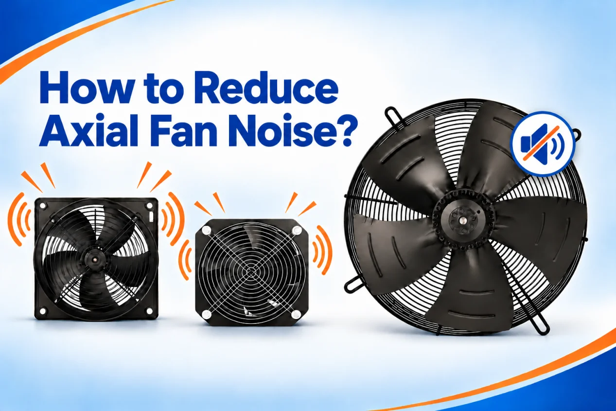
Cooling fans can become a significant source of noise in electronic equipment. Fan noise is influenced by both mechanical and aerodynamic factors. A cooling fan can introduce vibration into electronic equipment through motor rotation. If the fan is rigidly connected to the enclosure, this vibration can be transmitted to surrounding components and increase operating noise. Due to the narrow passages, abrupt airflow changes may create additional turbulence and further raise noise levels. Similarly, the noise level produced by the fans installed in the system will also differ from that specified in the product catalog.
Best Practices for Electronic Equipment Cooling
Determine Cooling Requirements
Since the failure rate of electrical components increases exponentially with rising temperatures, electrical equipment manufacturers recommend enclosure temperatures be kept between 10°C and 35°C (50°F to 95°F). Before selecting a cooling fan, identify the main heat-generating components and estimate the total heat that must be removed. The analysis should also consider the ambient temperature, enclosure size, and environmental conditions.
Design an Effective Airflow Path
The design of the cooling airflow path should start from the inlet, across critical heat-generating components, and toward the outlet. Poor component placement can block airflow or allow air to bypass areas that require cooling. High-heat components can generally be positioned closer to the exhaust side, while temperature-sensitive components benefit from receiving cooler inlet air. In some designs, baffles or ducts can also be used to direct airflow toward specific areas.
Consider System Resistance
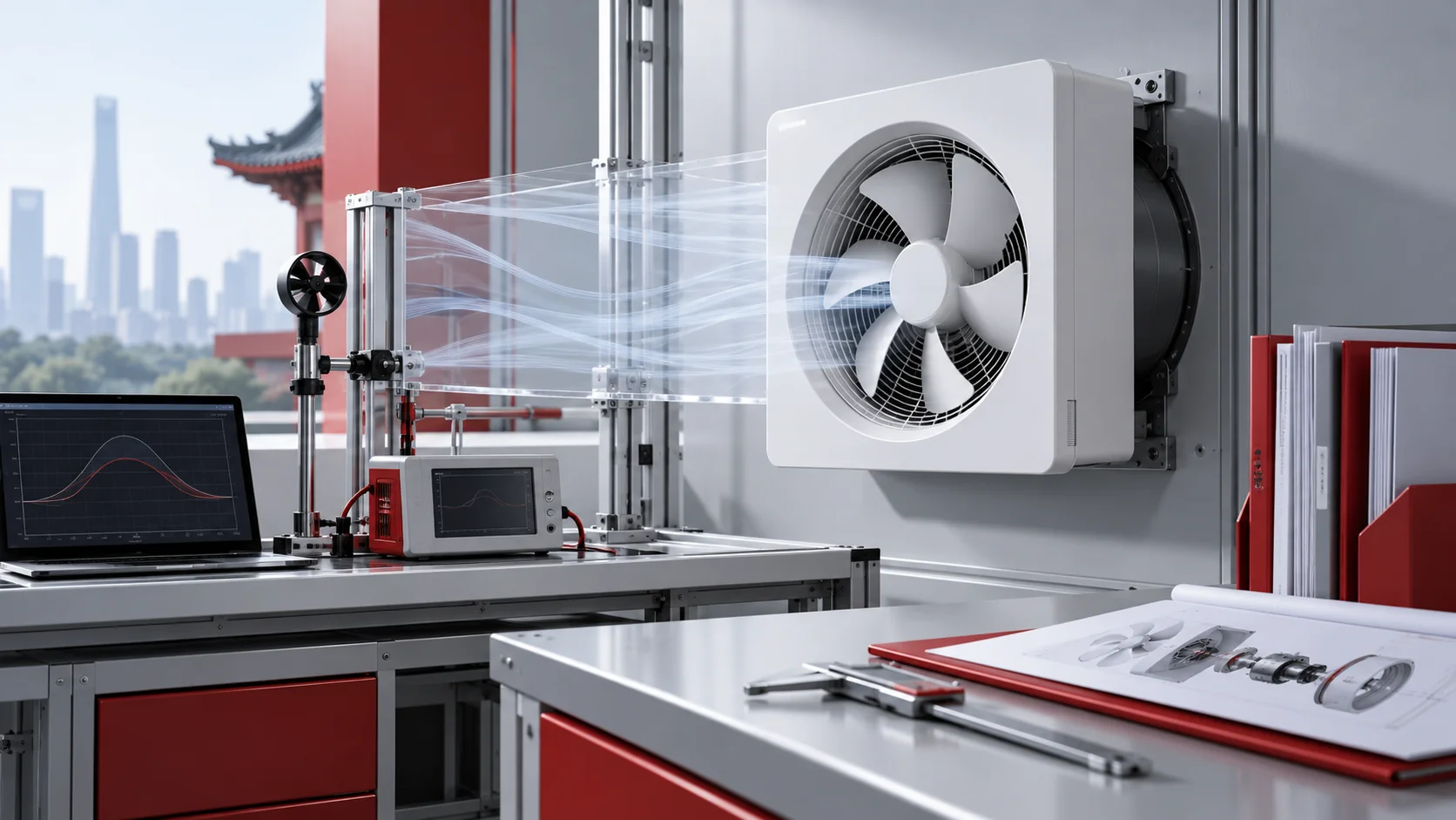
The airflow shown on a fan specification sheet is often measured under free-air conditions. Once the fan is installed, filters, grilles, heat sinks, PCBs, cables, and narrow passages resist the airflow, so the actual airflow volume will usually be lower.
For equipment with a restrictive airflow path, look beyond the free-air rating and check whether the fan can provide enough airflow at the required static pressure. The real operating point is where the fan P-Q curve meets the system resistance curve. If more cooling is needed, a fan with greater pressure capability may be a better choice.
Fan Redundancy
There are to common redundancy approaches, N+1 and N-1 redundancy. In an N+1 configuration, the system includes one additional fan beyond the number required to meet the normal airflow demand. The extra fan is a standby fan to take over if an operating fan becomes unavailable. In an N-1 mode, all installed fans have sufficient reserve capacity. They can increase their output if one fan fails. This allows the system to maintain the required total airflow without a dedicated standby fan.
Right Fan Types for Electronic Equipment Cooling
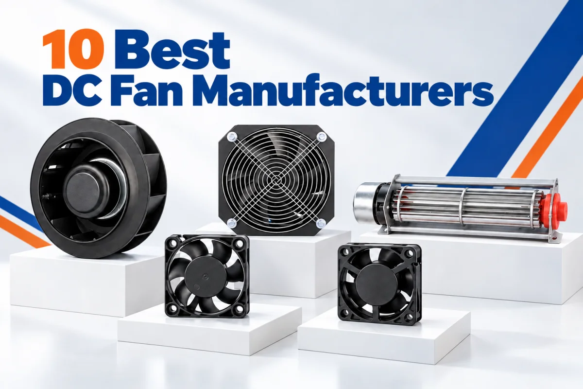
Axial Cooling Fan
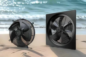
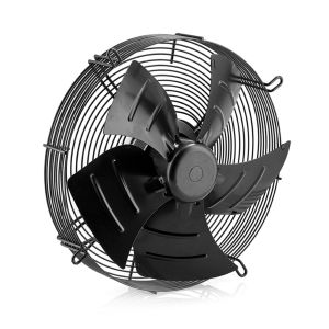
An axial fan moves air in the same direction as the shaft. It is usually installed on the outlet side of an enclosure to pull warm air out of the equipment. As air leaves, cooler air enters through filtered openings, creating a continuous airflow path through the enclosure. For electronic equipment, placement matters. The fan should be located where heated air can leave the enclosure without passing repeatedly around sensitive components. A clear intake-to-exhaust airflow path usually gives more effective heat removal.
Cross Flow Fan
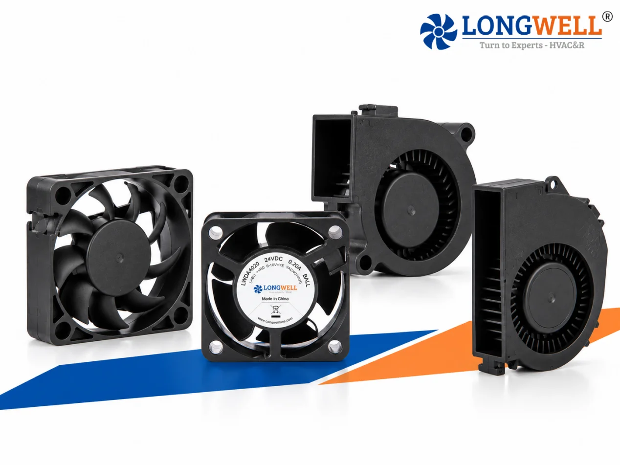
Cross flow fans move air along a wide outlet instead of concentrating it in a round airflow stream. Their long impeller makes them suitable for equipment that needs cooling across a broad section.
They are especially useful in long or narrow spaces where a conventional axial or centrifugal fan may be difficult to install. The fan can sit along the side of the equipment and provide airflow across a larger area.
Cross flow fans are particularly suitable when relatively uniform airflow is needed across multiple components or along an extended heat-generating surface. For electronic equipment with specific space and airflow-distribution requirements, a cross flow fan can therefore provide an alternative to axial or centrifugal designs.
LONGWELL Cooling Solutions for Electronic Equipment
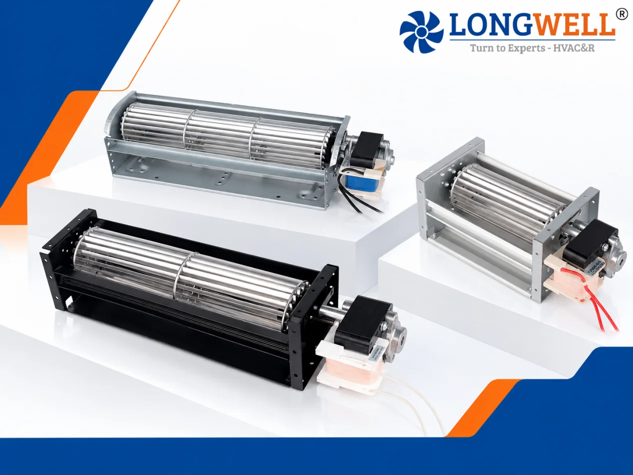
LONGWELL provides cooling solutions for electronic equipment. Rather than selecting a fan based on airflow alone, LONGWELL matches the fan configuration to the required air volume, static pressure, voltage, control mode, installation space, and system operating conditions.
For compact and rack-level electronic equipment, LONGWELL offers small DC axial fans for direct component and enclosure cooling. For higher-capacity systems such as CRAH and CRAC equipment, backward-curved EC plug fans provide the airflow and static-pressure capability required for more restrictive cooling paths. Multiple EC plug fans can be integrated into a FanGrid where higher airflow and reliability are required. The modular arrangement allows airflow capacity to scale with fan quantity, and supports centralized speed control.
These options allow OEM engineers to select or customize a cooling solution according to the thermal load, airflow resistance, control requirements, and reliability level of the electronic equipment.
FAQ
What are the signs that an electrical device is overheating?
You will notice a few things: the enclosure feels hotter than usual, the equipment trips on thermal shutdown more often, slower processing, lower power output, and the cooling fans never seem to ramp down.
What temperature destroys electronics?
Anything above 40°C (104°F) for long periods of operation will age components faster than normal service life. If the working temperature exceeds 80-100°C(176-212°F) continuously, permanent damage or actual failures will occur.
How do electrical cabinet fans prevent overheating?
They keep air moving through the box. Cool air comes in through the intake vents, picks up that thermal load, and gets pushed out the exhaust.